Brooks Instrument BM50 User Manual
Page 21
2-3
Section 2 Installation
Installation and Operation Manual
X-PD-BM-Ovals-eng
Part Number: 541B031AAG
January, 2009
BM Oval Series
2-6 Installation
To provide for optimum system performances the following guidelines
should be observed:
1. Before use, confirm the fluid to be used is compatible with the meter.
2. The flowmeter must be installed so the shafts of the rotors are
horizontal, never vertical or “on end”. Severe damage to components
may be the result, (See Figure 2-1).
3. A mesh strainer should be installed upstream and adjacent to the
flowmeter to protect it from foreign matter such as dirt, pipe scale,
or welding splatter.
Table 2-1 Maximum Particle Size and Recommended Strainer Mesh
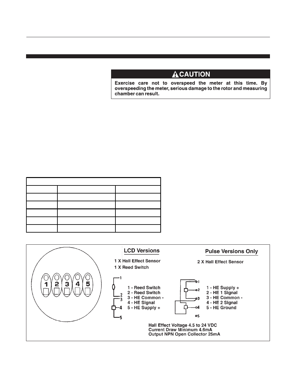
Figure 2-2 Hall Effect Sensor Connections
Strainer Recommendations
Model
Max Partical Size
Strainer Size
BM04
0.011" (0.28mm)
60 Mesh
BM07
0.011" (0.28mm)
60 Mesh
BM10
0.011" (0.28mm)
60 Mesh
BM40
0.015" (0.38mm)
60 Mesh
BM50
0.018" (0.46mm)
60 Mesh