Connection instructions #1, Connection instructions #2, Differential line driver – BEI Sensors Optical Isolator Interface Module User Manual
Page 2: Single ended line driver
Tel: 805-968-0782/800-350-2727 | Fax: 805-968-3154/ 800-960-2726 | 7230 Hollister Ave, Goleta, CA
93117-2807|
www.beisensors.com
Specification No. 02125-001 Rev 0713
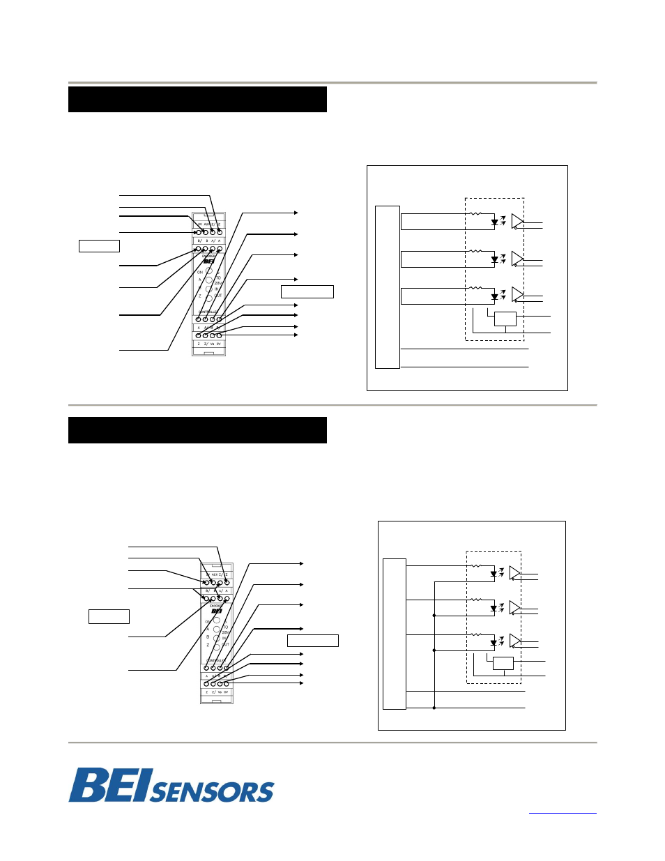
Differential Line Driver
Encoder signals from 5 VDC to 24 VDC (must specify the voltage when ordering)
This is the preferred type of encoder output as it has the best noise immunity. Connect each encoder signal to its like optical isolator
input (A to A, A/ to A/, etc).
Single Ended Line Driver
Encoder signal from 5 VDC to 24 VDC (must specify the voltage when ordering)
Connect encoder output A to optical isolator module input channel A, B to B and Z to Z. Connect the A/, B/, and Z/ inputs of the optical
isolator to circuit common of the encoder supply. Single ended operation is limited to shorter cable runs and is more susceptible to noise.
CONNECTION INSTRUCTIONS #1
Z
Z/
No Connection
No Connection
ENCODER
B/
B
A/
A
CONTROLLER
A
A/
B
B/
Z
Z/
Vs, 5V to 28V
0V, Power Common
A
A
A/
A/
B
B
B/
B/
Z
Z
Z/
Z/
+V
0V
A
A/
B
B/
Z/
Z
+V
0V
REG
VS
0V
Optical Isolator
Encoder Differential Line Driver Output
Figure 1
Standard Connection to
Optical Isolator Module
CONNECTION INSTRUCTIONS #2
A
A
A/
B
B
B/
Z
Z
Z/
+V
0V
A
A/
B
B/
Z/
Z
+V
0V
REG
VS
0V
Optical Isolator
Encoder Single Ended Line Driver Output
Figure 2
Connection Diagram
Single Ended Line Driver
Encoder
Supply
Z
No Connection
Connect A/, B/, Z/ to
Encoder Circuit
Common
ENCODER
B
A
CONTROLLER
A
A/
B
B/
Z
Z/
Vs, 5V to 28V
0V, Power Common
No Connection