BEI Sensors Optical Isolator Interface Module User Manual
Page 4
Tel: 805-968-0782/800-350-2727 | Fax: 805-968-3154/ 800-960-2726 | 7230 Hollister Ave, Goleta, CA
93117-2807|
www.beisensors.com
Specification No. 02125-001 Rev 0713
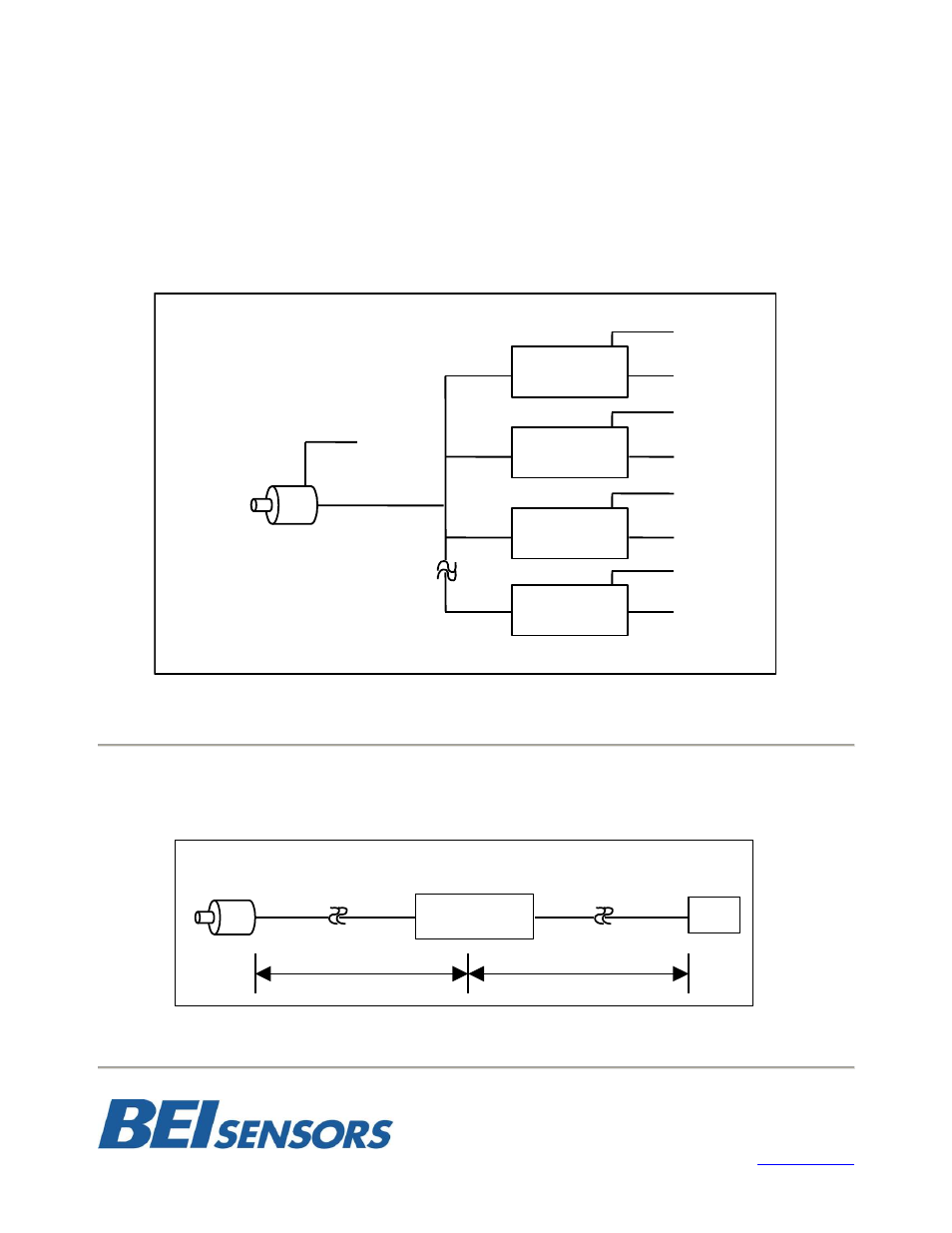
Example 2: Signal Splitter
The optical isolator can be used to connect a single encoder to multiple devices. Optical isolator can be used
to split an encoder output to drive up the 8 devices as shown in Figure 5. One optical isolator module is used
to drive each receiver. Optical isolator modules can be specified with outputs to match receiver inputs; i.e. an
encoder signal can be split to drive a differential TTL input with one module, a 12 V line driver with another
module and provide an open collector, NPN signal with another module.
* Also see the BEI Encoder Signal Broadcaster Module on page 5 for this application*
Example 3: Repeater
On extremely long cable runs (greater than 500 feet), an optical isolator module may be needed as a mid-
point repeater to receive, amplify and re-broadcast the signal. An example is illustrated in Figure 6.
Opto
Isolator
60001
-
003
FIGURE
5
CONNECTION DIAGRAM FOR
MULTIPLE,
NON
-
COMPATIBLE RECEIVERS
Opto
Isolator
60001
-
003
Opto
Isolator
60001
-
003
Opto
Isolator
60001
-
002
Encoder
Supply V
5V Logic
Line Driver
5V Output
Maximum of 8 Optical Isolator Modules
24V Supply
24V Logic
12
V Supply
12
V Logic
5
V Supply
5
V Logic
24V Supply
5
V Logic
Optical Isolator
Module
PLC
500’
500’
FIGURE 6
REPEATER FOR VERY LONG CABLE RUNS