Connection instructions #3, Uses for optical isolator module – BEI Sensors Optical Isolator Interface Module User Manual
Page 3
Tel: 805-968-0782/800-350-2727 | Fax: 805-968-3154/ 800-960-2726 | 7230 Hollister Ave, Goleta, CA
93117-2807|
www.beisensors.com
Specification No. 02125-001 Rev 0713
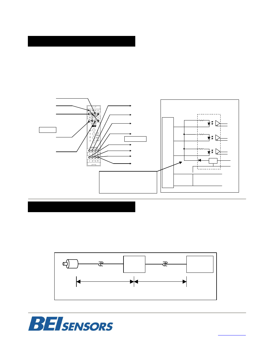
Open Collector with or without Internal Pull-up Resistors
Encoder NPN (sinking) outputs.
Connect encoder output A to optical isolator module input A/, B to B/ and Z to Z/. Connect the A, B, and Z
inputs of the optical isolator to the auxiliary output terminal on the optical isolator module for 5V module and to
higher voltage when specified by module model and part number. This connection results in a logic inversion
within the optical isolator module. To compensate for the logic reversal, swap A for A/, B for B/, and Z for Z/
at the optical isolator outputs.
Example 1: Resolve an electrical conflict between encoder output and receiving electronics
Sometimes system constraints result in an incompatibility between the encoder output and the receiving electronics or the
cabling. A typical symptom of this problem is missed or intermittent counts. As an example, a single-ended TTL receiver
that is more than 20 feet from the encoder may not be able to compensate for the signal attenuation and ringing caused
by the encoder cabling. An optical isolator module installed near the receiver as shown in Figure 4 can receive the signal,
rejecting the cable effects and produce a signal compatible with the input device.
CONNECTION INSTRUCTIONS #3
Z
Encoder Circuit
Common
ENCODER
B
A
CONTROLLER
A/
A
B/
B
Z/
Z
Vs, 5V to 28V
0V, Power Common
+5 Output
A or A/
A
A/
B or B/
B
B/
Z or Z/
Z
Z/
+V
0V
A
A/
B
B/
Z/
Z
+V
0V
REG
VS
0V
Optical Isolator
Encoder Open Collector Output
Figure 3
Connection Diagram
Open Collector to Optical Module
Optical Regulation
Power Supply
AUX
5V
Uses for Optical Isolator Module
Optical
Isolator
Module
TTL
Single-Ended
Receiver
> 20’
< 6’
FIGURE 4
LONG CABLE RUN TO SINGLE ENDED INPUT
To 5 AUX for 5V module.
To 12-15 for 24V dependent
on specified module input
voltage.