BEI Sensors Optical Isolator Interface Module User Manual
Optical isolator, Electronic module
Tel: 805-968-0782/800-350-2727 | Fax: 805-968-3154/ 800-960-2726 | 7230 Hollister Ave, Goleta, CA
93117-2807|
www.beisensors.com
Specification No. 02125-001 Rev 0713
OPTICAL ISOLATOR
ELECTRONIC MODULE
Output Code Format
From Encoder
Dual Channel in quadrature plus index and complements. Data lines are designated A, B, Z, A/, B/, Z/ at the
module
Output Signal Type
From Encoder
Differential line driver (Use Connection Instructions #1)
Single ended line driver (Use Connection Instructions #2)
Single ended open collector with pull-up resistors internal to encoder (Use Connection Instructions #3)
Single ended, open collector (Use Connection Instructions #3)
Output Signal
Voltage Level From
Encoder
5 VDC (TTL, RS422 compatible, line driver)
12-15 VDC
24VDC
Frequency Response
of Optical Isolator
1 MHz, maximum
Power Requirements
For Optical Isolator
5-28 VDC ±5%, 75mA plus load current
Optical Isolator
Output Options
28V/V Line Driver, 100mA source/sink, Vout = Vin
28V/5 Line Driver, 100mA source/sink, Vout = 5V (Derate output current to 50mA with supply voltage > 12VDC)
28V/OC NPN Open Collector, 80mA sink
Protection Level
Supply lines protected against over voltage to 60 volts and reverse voltage
Tristate Outputs
Available as
–S Special Feature
ELECTRICAL SPECIFICATIONS
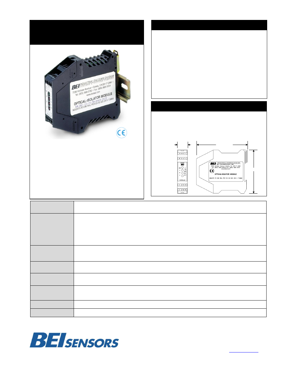
MECHANICAL SPECIFICATIONS
Package dimensions are 114.4 mm high by 99 mm wide by 22.5
mm thick. The package mounts to a DIN rail type EN 50 022
(35mm X 7.5mm). A length of DIN rail is supplied with each
module. The module simply snaps directly to the DIN rail and is
ready to use.
22.5 mm
(0.89 inches)
114.5 mm
(4.51 inches)
99 mm
POWER:
The optical isolator can accommodate standard operating
voltages from 5 to 28 VDC. It should never be connected
directly to AC power mains. The module draws approximately
75 mA and a green LED indicates the unit is powered. The
optical isolator module does not provide power to the encoder.
Any encoders used in conjunction with this module must be
connected to their own power.
SIGNAL:
Specifying an optical isolator module requires knowledge of
three system parameters: the DC supply voltage available in the
system; the encoder output type (logic levels and driver type);
and the input signal specifications of the receiving electronics.
This is a versatile interface between an incremental
encoder and receiving electronics. It accepts single
ended or differential inputs and provides single ended or
differential outputs in either an open collector or line
driver configuration. It accommodates all standard
operating voltages from 5 to 28 VDC. Up to eight Optical
Isolator Modules can be daisy-chained to provide
multiple, simultaneous outputs to controllers or PLC’s.
This Optical Isolator can help clean up noisy signals by
converting to a different line driver output. It has a 1
MHz throughput capability and can be used wherever a
fast, optically isolated interface is required.