Advanced settings – CHIEF PXR User Manual
Page 23
Installation Instructions
PXR
23
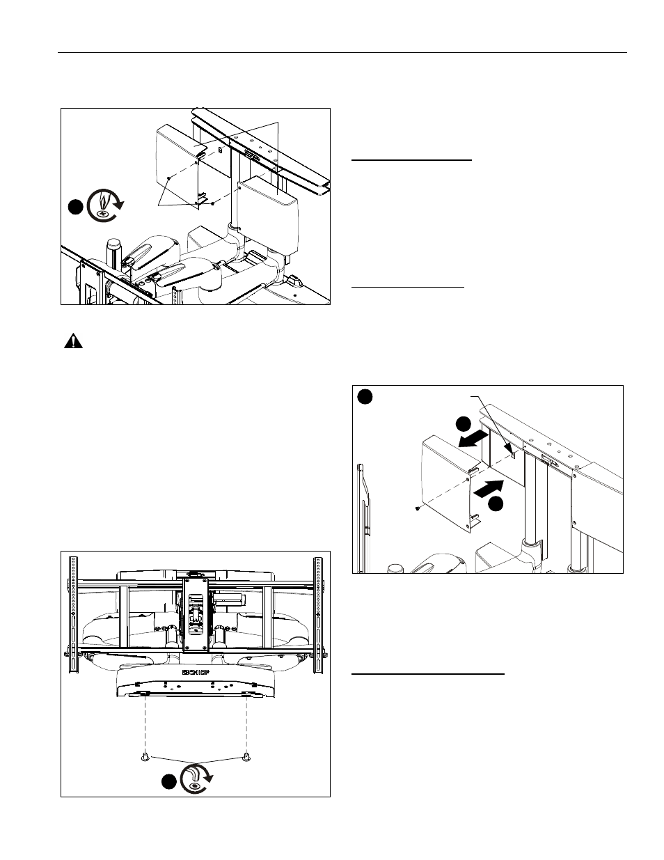
3.
Add plastic covers (P) to PXR, fastening with two
8-32 x 1/4" Phillips flat head screws (S). (See Figure 41)
Figure 41
WARNING:
If the display is changed, cables are re-routed,
or an accessory is added/removed, it is best to recalibrate the
PXR by going through the learn mode sequence. Failure to
do so may lead to injury.
4.
Use Velcro disc (shipped with IR receiver) to attach the IR
sensor (AA) in a convenient location for your installation.
IMPORTANT ! : Ensure that IR sensor "eye" has line-of-
sight to the remote control signal.
Final Attachment to Wall Mounting Bracket
NOTE:
For wood stud and concrete wall installations only.
1.
Make final attachment of PXR to wall mounting bracket
using two 8-32 x 3/8" buttonhead cap screws (T). (See
Figure 42)
Figure 42
ADVANCED SETTINGS
NOTE:
Normal operation is a green light slowly fading on/off
(seen through main control board housing).
NOTE:
If red light is on without blinking, the IR receiver cable
may not be completely plugged in.
IR Repeat Conditions
NOTE:
The PXR is equipped with a built-in IR repeater that
works with most IR transmitters (38kHz).
NOTE:
The IR repeater cable must have a 3.5mm Mono plug.
1.
Plug an IR repeater cable (not included) into the I/O board.
(See Figure 3)
2.
Route IR repeater cable to the desired device.
Heavy Screen Mode
NOTE:
The PXR is equipped with a "Heavy Screen Mode" that
allows it to compensate for heavy or thick screens. By
enabling this feature, the PXR will gain an additional
2°-3° of upward tilting.
1.
Remove the plastic cover from the main circuit board. (See
Figure 43)
Figure 43
2.
Use a small screwdriver or small pointed object to flip DIP
Switch 1 on the main control board to the "off" position. (See
Figure 43)
3.
Replace plastic cover over main circuit board.
Emergency Service Extend
In the event the PXR needs to be serviced while inside a
recessed wall, use the following command sequence to extend
the unit out of the recess. This feature is only available in units
with software version 40 or greater.
1.
Hold save for 5 seconds, then Press Pan Right, Press Pan
Left, Press and hold Extend button for up to 20 seconds of
movement.
2.
The speed is 1/2 the normal extend speed. At the end of the
20 seconds the unit will time out. Repeat as necessary to
get the unit to the desired service position.
3
(S) x 2
(P)
1
(T) x 2
1
2
Access DIP switches
for Heavy Screen Mode
3