CEMB USA SM56T User Manual
Page 18
18
10
IDENTIFICAZIONE COMANDI
10
IDENTIFYING CONTROLS
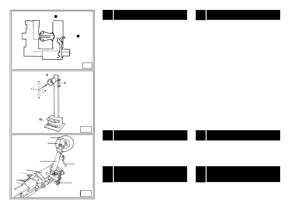
La colonnetta mobile porta comandi (fig. C) consente all'operatore
di scegliere la posizione di lavoro di volta in volta più conveniente.
Su questa colonnetta sono concentrati tutti i comandi; più precisa-
mente:
- Il manipolatore (8, fig. C) in posizione [a] alza il braccio porta-
autocentrante; in posizione [b] lo abbassa; in posizione [c] avvicina
il carrello porta-utensili e la pedana mobile all'autocentrante, in po-
sizione [d] lo allontana.
(Nota: per meglio memorizzare quest'ultima operazio-ne, sulla pro-
tezione del manipolatore è stato praticato un foro in corrispondenza
della posizione [c]).
- L'interruttore (9, fig. C) azionato verso l'alto apre i bracci
dell'autocentrante (BLOCCA); azionato verso il basso chiude i brac-
ci dell'autocentrante (SBLOCCA).
- Il pedale a bilanciere (10, fig. C) consente, se azionato in uno dei
due lati, di far ruotare l'autocentrante in un senso o nell'altro come
indicato dalle frecce poste sulla pedaliera.
Entrambe le rotazioni possono avenire con due diverse velocità pre-
disponendo il commutatore (12, fig. B/6) in posizione 1 per la rota-
zione lenta e in pos. 2 per una rotazione veloce dell'autocentrante.
Sullo smontagomme sono inoltre presenti:
Il pedale (15, Fig. D) che consente il ribaltamento del braccio porta
utensile (14, Fig. D) dalla posizione di lavoro a quella di fuori lavoro
e viceversa.
La maniglia (19, Fig. D) che consente di utilizzare alternativamente
il disco stallonatore (17, fig. D),o l'utensile a becco (18, fig.D).
Nello schema B/8 vengono riportate varie posizioni di lavoro
(A, B, C, D) che saranno poi richiamate durante le istruzioni
d'uso dello smontagomme. Operare dalle posizioni indicate
consente maggiore precisione, velocità e sicurezza per chi
opera.
The diagram B/8 illustrates the various working positions
(A,B,C,D) referred to in the following pages describing how to
use the tyre changer. Use of these positions ensures greater
precision, speed and safety for those using the machine.
The mobile control centre (fig. C) enables the operator to work at
any position around the machine. On this mobile control centre the
following controls are located:
-The lever (8, fig. C) which in position [a] lifts the chuck arm and in
position [b] lowers it; in position [c] moves the tool holder arm and
the sliding table towards the self-centering chuck and in position [d]
moves them away.
(Note: in order to memorise this operation, there is a hole in the
lever guard corresponding to position c).
-The chuck switch (9, fig. C) when moved upwards, opens the arms
of the self-centering chuck (LOCKING), and when moved down,
closes the arm of the self-centering chuck (UNLOCKING).
-The pedal (10, fig. C) when pressed on the left or right side rotates
the self-centering chuck in the same direction as shown by the ar-
rows placed on the foot pedal.
Both rotations can be made with two different speeds, just placing
the selector (12, fig. B/6) in position 1 for getting slow rotation and in
position 2 for fast rotation of the turntable
The tyre changer also has:
Pedal (15, Fig. D) to tip the tool carrier arm (14, Fig. 4) from its work
to its non-working position and vice-versa.
Handle (19, Fig. D) that permits alternative use of the bead-break-
ing disk (17, Fig. D) or the hooked tool (18, Fig. D).
POSIZIONE DI LAVORO
11
WORKING POSITION
Prima di iniziare ad utilizzare lo smontagomme sono necessari
alcuni controlli per verificarne il corretto funzionamento.
ATTENZIONE: Le operazioni che seguono vanno effettuate con
il braccio portautensili in posizione di "fuori lavoro".
CONTROLLO CORRETTO
FUNZIONAMENTO
12
CORRECT OPERATION
CHECKS
12
Before using the tyre changer, a number of checks should be
made to ensure it works correctly.
CAUTION! The operations described here should be done with
the tool carrier arm in its non-working position.
B/8
D
C
11
a
b
c
d
18
14
13
19
15
17