Electric hook up, B/6 allacciamento elettrico, B/7 12 5 – CEMB USA SM56T User Manual
Page 12
12
7.3
7.3
ELECTRIC HOOK UP
B/6
ALLACCIAMENTO ELETTRICO
Prima di effettuare qualsiasi collegamento elettrico controlla-
re attentamente che la tensione di rete corrisponda con quan-
to riportato sul cartellino voltaggio (posizionato in prossimità
della spina dello smontagomme).
E' assolutamente obbligatorio che :
- l'impianto sia corredato di una buona rete di terra.
- la macchina sia collegata ad interruttore differenziale tarato
a 30 mA.
- la presa di corrente sia adeguatamente protetta contro le
sovra correnti con fusibili o interruttore automatico
magnetotermico con valori nominali come da tabella qui ri-
portata.
Leggere sull'apposita targhetta dati, situata sullo smontagom-
me, l'assorbimento richiesto e verificare se la rete elettrica in
questione è sufficientemente dimensionata.
Interventi sull'impianto elettrico, anche di
lieve entità, richiedono l'opera di
personale professionalmente qualificato.
Ogni danno derivante dalla mancata osservanza delle sud-
dette indicazioni non sarà addebitabile al costruttore e com-
porterà la decadenza delle condizioni di garanzia.
220 V. - 3 Ph. - 50/60 Hz.
240 V. - 3 Ph. - 50/60 Hz.
380 V. - 3 Ph. - 50/60 Hz.
415 V. - 3 Ph. - 50/60 Hz.
Corrente nominale
25 A AM
25 A AM
16 A AM
16 A AM
Alimentazione
Interrutt.
Fusibile
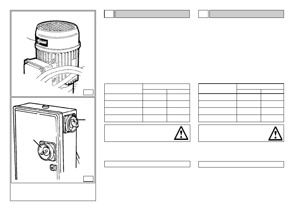
Collegare lo smontagomme alla rete, azionare l'interruttore genera-
le (5, fig. B/7) e verificare che il senso di rotazione del motore della
centralina oleodinamica sia quello indicato dalla freccia (6, fig. B/6).
In caso contrario fare invertire tra loro, da personale specializzato,
due fili nella spina .
CONTROLLO SENSO DI ROTAZIONE
Before making any electric hook up, check to be certain that
the mains voltage corresponds to that stamped on the voltage
tag (attached to the cord near the tyre changer’s plug).
It is absolutely essential that :
- the system is equipped with a good grounding circuit.
- The machine is connected to a power supply line circuit
breaker set for 30 mA.
- The current instake is adeguately protected against
overcurrents with fuses or automatic magneto-thermic switch
with rated values as swohn in the table B/8.
Note the required power draw as highlighted on the data plate
fixed to the tyre changer. Check to make sure the shop elec-
tric wiring circuit is dimensioned sufficiently to carry this.
Work on the electric system, even if minor,
must be done exclusively by
professionally qualified personnel.
Manufacturer shall not be liable for any injury to persons or
damage to things caused by failure to comply with these regu-
lations and can cancel warranty coverage.
220 V. - 3 Ph. - 50/60 Hz.
240 V. - 3 Ph. - 50/60 Hz.
380 V. - 3 Ph. - 50/60 Hz.
415 V. - 3 Ph. - 50/60 Hz.
Rated current
25 A AM
25 A AM
16 A AM
16 A AM
Power supply
Fuse
Connect the machine to the mains, switch “ON” (5, fig. B/7) and
check that the gearbox motor rotation corresponds to the indicating
arrow (6, fig. B/6).
If not, switch two wires in the plug .
SENSE OF ROTATION CHECKS
Switch
25 A
25 A
16 A
16 A
25 A
25 A
16 A
16 A
B/7
12
5
6