C.E. Niehoff & Co. N1610 Troubleshooting Guides User Manual
Page 5
Page 5
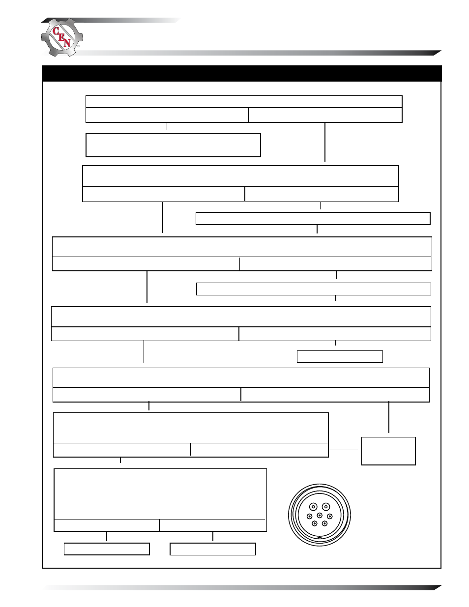
TG61B
Shut off engine. With key off, engine off: Test for battery voltage at alternator 28 V B+
terminal. Does battery voltage exist?
Yes
No
Repair vehicle ignition circuit wiring as necessary. Continue test.
Chart 1 — No 28V Alternator Output – Test Charging Circuit
With DMM, check resistance across field coil. Connect red lead of DMM to socket C in alternator-to-regulator
harness plug. Connect black lead to B+ terminal on alternator. Does meter show 1.5 ± 0.2 ohms?
Yes
No
STATIC TEST – KEY ON, ENGINE OFF
Yes
Test phase signal into regulator (AC). Set meter to diode tester:
Connect red lead of DMM to socket A of regulator harness and
black lead to socket B. Meter should show voltage drop value.
Then reverse meter lead connections. Meter should show OL
(blocking).
No
Shut down vehicle and restart engine. Does alternator function normally after restart?
Yes
No
Figure 3 – Alternator-to-Regulator
7-Socket Harness Plug
With key on, engine running: Test for battery voltage between IGN terminal on regulator and alternator B–
terminal. Does 28 V battery voltage exist?
Yes
No
With key off, engine off: Remove alternator-to-regulator 7-pin harness from regulator. Test for battery
voltage across sockets A and D in harness plug. Does 28 V battery voltage exist?
Alternator is defective.
Alternator is
defective.
Alternator is defective.
Regulator is defective.
A
B
C
D
E
F
G
Yes
Connect jumper wire from socket C in regulator harness plug to B– terminal on
alternator and momentarily (1 sec.) jump pin F to B+. Spark will occur. Touch
steel tool to shaft to detect significant magnetism. Is shaft magnetized?
No
Repair vehicle ignition circuit wiring as necessary. Continue test.
Yes
No
Section C: Advanced Troubleshooting
(CONT’D)
Regulator responded to overvoltage condition.
Go to Chart 3 on page 6 to troubleshoot OVCO.
SOCKET CONNECTIONS
IN ALTERNATOR PLUG
A B−
B AC
C F−
D B+
E TS
F F+
G Not used