N3243 regulator – C.E. Niehoff & Co. N1609 Troubleshooting Guides User Manual
Page 4
Page 4
TG50E
TABLE 3—N3240 Regulators
LED Indications and Status
Indication
Status
GREEN ON steady
Normal regulator operation.
Alternator is producing output.
GREEN FLASHING Regulator waiting for alternator
to begin rotation.
AMBER ON steady
System voltage is high.
AMBER FLASHING OVCO activated.
Off (Clear)
Regulator is not working/
energize signal is not present at
IGN terminal.
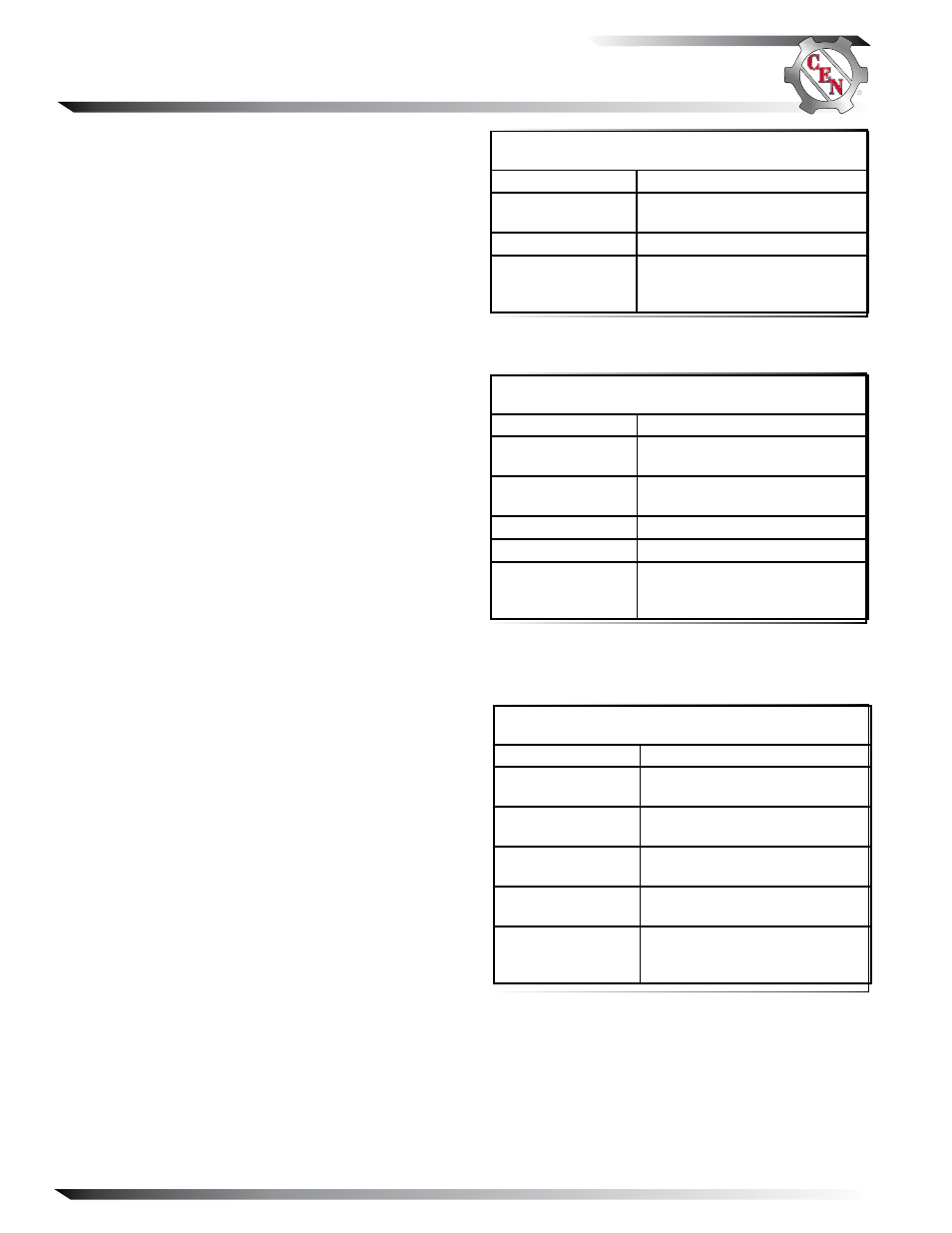
TABLE 2—N3243 Regulator
LED Indications and Status
Indication
Status
GREEN ON steady
Normal regulator operation.
Alternator is producing output.
GREEN FLASHING OVCO activated
Off (Clear)
Regulator is not working/
energize signal is not present at
IGN terminal.
TABLE 4—N3256 Regulators
LED Indications and Status
Indication
Status
GREEN ON steady
Normal regulator operation.
Alternator is producing output.
GREEN FLASHING Regulator waiting for alternator
to begin rotation.
AMBER ON steady
Voltage below setting and during
10 second ramp up.
AMBER FLASHING Regulator has shut down due to
overvoltage.
Off (Clear)
Regulator is not working/
energize signal is not present at
IGN terminal.
NOTE: N3240 regulator–if any other color appears or if unsure
of the color, verify voltage at alternator.
N3243 Regulator
DeSCrIptION AND OperAtION
N3243 regulator with OVCO is attached directly to
the outside of alternator.
Main diagnostic feature of regulator consists of a green-
lensed LED located on the side of the regulator. LED
works like a voltmeter, measuring charging voltage. See
Table 2 for diagnostic features and LED explanations.
Regulator will trip OVCO when system voltage rises
above 31.5 V for longer than 2 seconds. OVCO feature
detects high voltage and reacts by signaling relay in field
circuit to open, turning off alternator. Restarting engine
or waiting until system voltage drops to setpoint will
reset OVCO circuit.
N3240 and N3256 Regulator
DeSCrIptION AND OperAtION
N3240 and N3256 regulators with OVCO are attached
directly to the outside of alternator.
Main diagnostic feature of the regulator is a bicolored
LED next to the harness receptacle on regulator. LED
works like a voltmeter, measuring charging voltage.
See Tables 3 and 4 for diagnostic features and LED
explanations.
Regulator will trip OVCO when system voltage rises
above 31.5 V for longer than 2 seconds. OVCO feature
detects high voltage and reacts by signaling relay in field
circuit to open, turning off alternator. Restarting engine
or waiting until system voltage drops to setpoint will
reset OVCO circuit.
Troubleshooting
Shut down vehicle and restart engine. If alternator
functions normally after restart, a “no output condition”
was normal response of voltage regulator to overvoltage
condition. Inspect condition of electrical system, includ-
ing loose battery cables, both positive and negative. If
battery disconnects from system, it could cause over-
voltage condition in electrical system, causing OVCO
circuit to trip.
If you have reset alternator once, and electrical system
returns to normal charge voltage condition, there may
have been a one time, overvoltage spike that caused
OVCO circuit to trip.
If OVCO circuit repeats cutout a second time in short
succession and shuts off alternator field circuit, try
third restart. If OVCO circuit repeats cutout a third
time, check color of LED while engine is running and go
to Chart 2, page 6.
Section C: Advanced Troubleshooting