Cen n1609 alternator description and operation – C.E. Niehoff & Co. N1609 Troubleshooting Guides User Manual
Page 2
Page 2
TG50E
Section A: Wiring Diagram
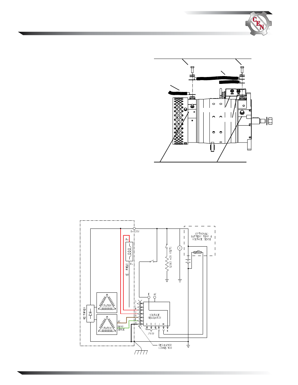
Figure 2 — N1609 Wiring Diagram
Figure 1 — N1609 Alternator and Regulator Terminals
AC terminal
IGN terminal
B+ connections on alternator
Both positive cables must be connected together at battery posi-
tive potential when alternator is installed in vehicle and during
operation. Interconnect cable is not part of vehicle cabling.
Interconnect
cable
Positive cables
from vehicle
CEN N1609 Alternator
Description and Operation
N1609 28 V (570 A) alternator is internally rectified.
All windings and current-transmitting components are
non-moving, so there are no brushes or slip rings to
wear out. Energize switch activates regulator. Field coil
is then energized.
After engine is running,
N3240, N3243 or N3256
regulator furnished with some units receives energize
signal. Regulator monitors alternator rotation and pro-
vides field current only when it detects alternator shaft
rotating at suitable speed.
After regulator detects alternator rotation, it gradually
applies field current, preventing an abrupt mechanical
load on accessory drive system.
The soft start may take up to 10 seconds at full electri-
cal load.
These regulators:
• are negative temperature compensated.
• maintain alternator output voltage at regulated
settings as vehicle electrical loads are switched
on and off.
• provide overvoltage cutout (OVCO).
• are equipped with remote battery temperature and
voltage sensing circuits. If no external sensors are
used, the regulator will regulator the alternator volt-
age based on the position of voltage select switch on
the backside of the regulator. When sensors are used
they will optimize the charging voltage, so the volt-
age select switch should be positioned according to
the type and location of batteries.
N3243 regulator also provides limp home capability
when regulator detects a problem in the alternator/
regulator. Restarting engine will reset regulator.
B– connections on alternator
Both ground cables must be connected together at battery
ground potential when alternator is installed in vehicle and dur-
ing operation. Interconnect cable is not part of vehicle cabling.
BR
BK
G
W
R
R