Warning – C.E. Niehoff & Co. N1450 Troubleshooting Guides User Manual
Page 4
Page 4
TG57B
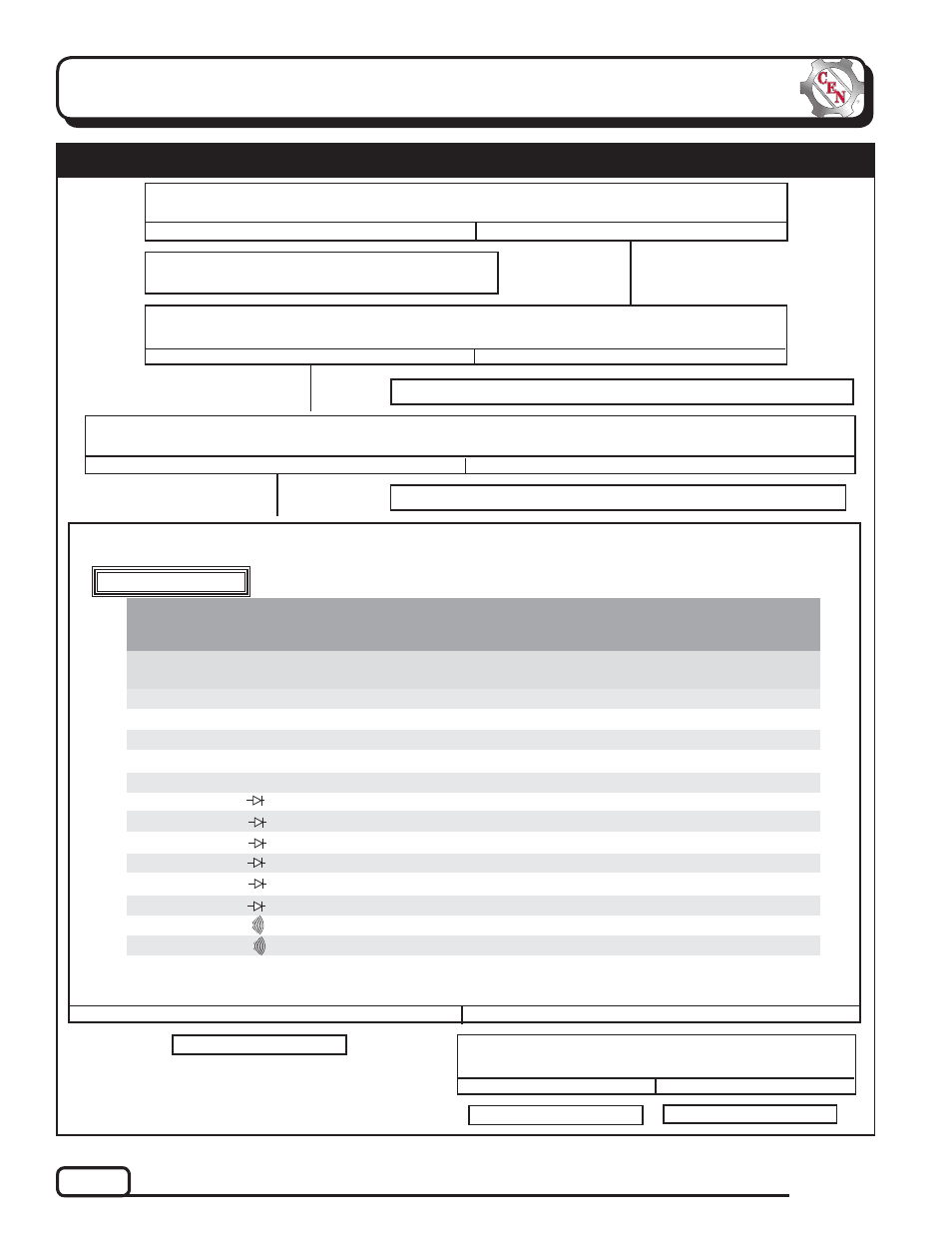
Section C: Advanced Troubleshooting
Shut off engine. With key off, engine off: Test for battery voltage at alternator B+1 terminal
connected to battery. Does battery voltage exist?
Yes
No
Chart 1 – No Alternator Output – Test Charging Circuit
Shut down vehicle and restart engine or wait until system voltage drops below 28 V. Does alter-
nator function normally after restart?
Yes
No
Disconnect 3-socket harness plug from regulator. With key on, engine running: Test for battery voltage between
pin B in 3-pin connector on regulator and alternator B– terminal. Does battery voltage exist?
Yes
No
MASTER BATTERY SWITCH OFF, KEY OFF, ENGINE OFF: Reconnect 3-socket harness to regulator. Discon-
nect alternator-to-regulator harness at regulator. Follow static tests in Table 2. Has any test result failed?
Alternator is defective.
Repair vehicle ignition circuit wiring as necessary. Continue test.
Yes
No
Regulator responded to overvoltage condition.
Go to Chart 2 on page 5 to troubleshoot OVCO.
Repair vehicle battery circuit wiring as necessary. Continue test.
Regulator is defective.
Alternator should not be powered during static tests. Connections required during
testing can cause shorts and damage alternator.
WARNING
TABLE 2 Pin-to-Pin Tests (See Figure 3)
DISCONNECT ALTERNATOR-TO-REGULATOR WIRING HARNESS AT REGULATOR.
TESTS MUST BE PERFORMED AT ROOM TEMPERATURE.
METER SCALE
& SYMBOL
METER (+) LEAD
CONNECTION
EXPECTED
READING
METER (–) LEAD
CONNECTION
TESTED CIRCUIT
Pin J
Pin M
Pin L
Pin E
Pin G
Alt. B– Terminal
Alt. B– Terminal
Alt. B+ 1 Terminal
Alt. B– Terminal
Alt. B+ 2 Terminal
Alt. B– Terminal
Pin A
Alt. B+ 1 Terminal
Pin K
Alt. B– Terminal
Alt. B+ 1 Terminal
Alt. B+ 2 Terminal
Pin H
Pin A
Pin B
Alt. B– Terminal
Alt. B+ 1 Terminal
Alt. B– Terminal
Alt. B+ 2 Terminal
Pin B
Alt. B+ 2 Terminal
Field circuit
Ground circuit
Power circuit (B+ 1)
Power circuit (B+ 2)
Stator temp sensor
Phase circuit (P1)
Phase circuit (P2)
All diodes in parallel (B+ 1)
All diodes in parallel (B+ 1)
All diodes in parallel (B+ 2)
All diodes in parallel (B+ 2)
Stator-to-stator continuity
B+ 1 to B+ 2 continuity
5–6 ohms
<1 ohm
<1 ohm
<1 ohm
90K to 120K ohms
See NOTE 1
See NOTE 1
OL*(blocking)
<0.7 volt**(flow)
OL*(blocking)
<0.7 volt**(flow)
OL (blocking)
OL (blocking)
* Meter will show OL when capacitors are fully charged and readings stabilize.
** Meter will show voltage drop of all diodes in parallel when capacitors are fully charged and readings stabilize.
NOTE 1: If PC board is present, <0.7 volt (flow). If not present, <0.3 volt (flow).
TEST
NO.
1
2
3
4
5
6
7
8
9
10
11
12
13
Ohms Ω
Ohms Ω
Ohms Ω
Ohms Ω
Ohms Ω
Diode Test
Diode Test
Diode Test
Diode Test
Diode Test
Diode Test
Continuity
Continuity
Replace regulator with known good regulator. Run engine.
Does no-output condition still exist?
Yes
No
Alternator is defective.