Cen n1450 alternator description and operation – C.E. Niehoff & Co. N1450 Troubleshooting Guides User Manual
Page 2
Page 2
TG57B
Section A: Wiring Diagram
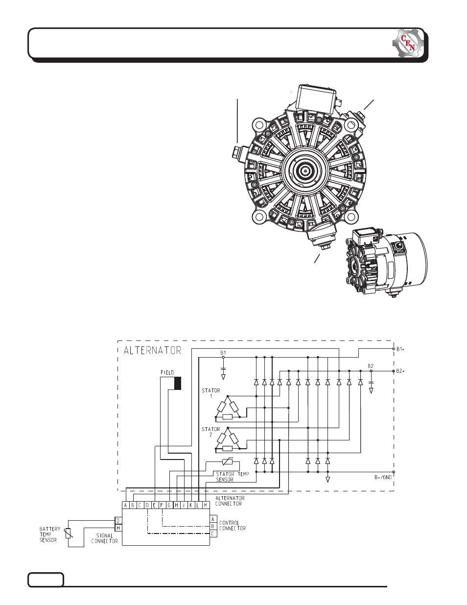
Figure 2 — N1450 Wiring Diagram
Figure 1 — N1450 Alternator Terminals
B+
1 primary
(high load)
output
terminal.
Battery must
be connected
to this terminal
for unit to be
energized.
CEN N1450 Alternator
Description and Operation
N1450 28 V (400 A) alternator is internally rectified.
There are no brushes or slip rings to wear out.
Energize switch activates regulator. Exciter stator
is then energized.
After engine is running, the regulator receives energize
signal. Regulator monitors alternator rotation and pro-
vides field current only when it detects alternator shaft
rotating at suitable speed.
N3227 or N3250 regulator used with some units:
• is negative temperature compensated.
• maintains alternator output voltage at regulated
settings as vehicle electrical loads are switched
on and off.
• provides overvoltage cutout (OVCO). Regulator will
trip OVCO when system voltage rises above 32 V for
longer than 3 seconds. OVCO feature detects high
voltage and reacts by disconnecting field and turning
off alternator. Restarting engine or waiting until
system voltage drops below 24 V will reset OVCO
circuit.
B– terminal
B+2 secondary
(low load)
output
terminal