Can/j1939 interface – C.E. Niehoff & Co. N1335 Troubleshooting Guides User Manual
Page 3
Page 3
TG0052A
Section 2: CAN/J1939 Diagnostics
CAN/J1939 Interface
DESCRIPTION AND OPERATION
The CEN N3234 digital regulator is compatible with
SAE J1939 communications standard for vehicle
networking.
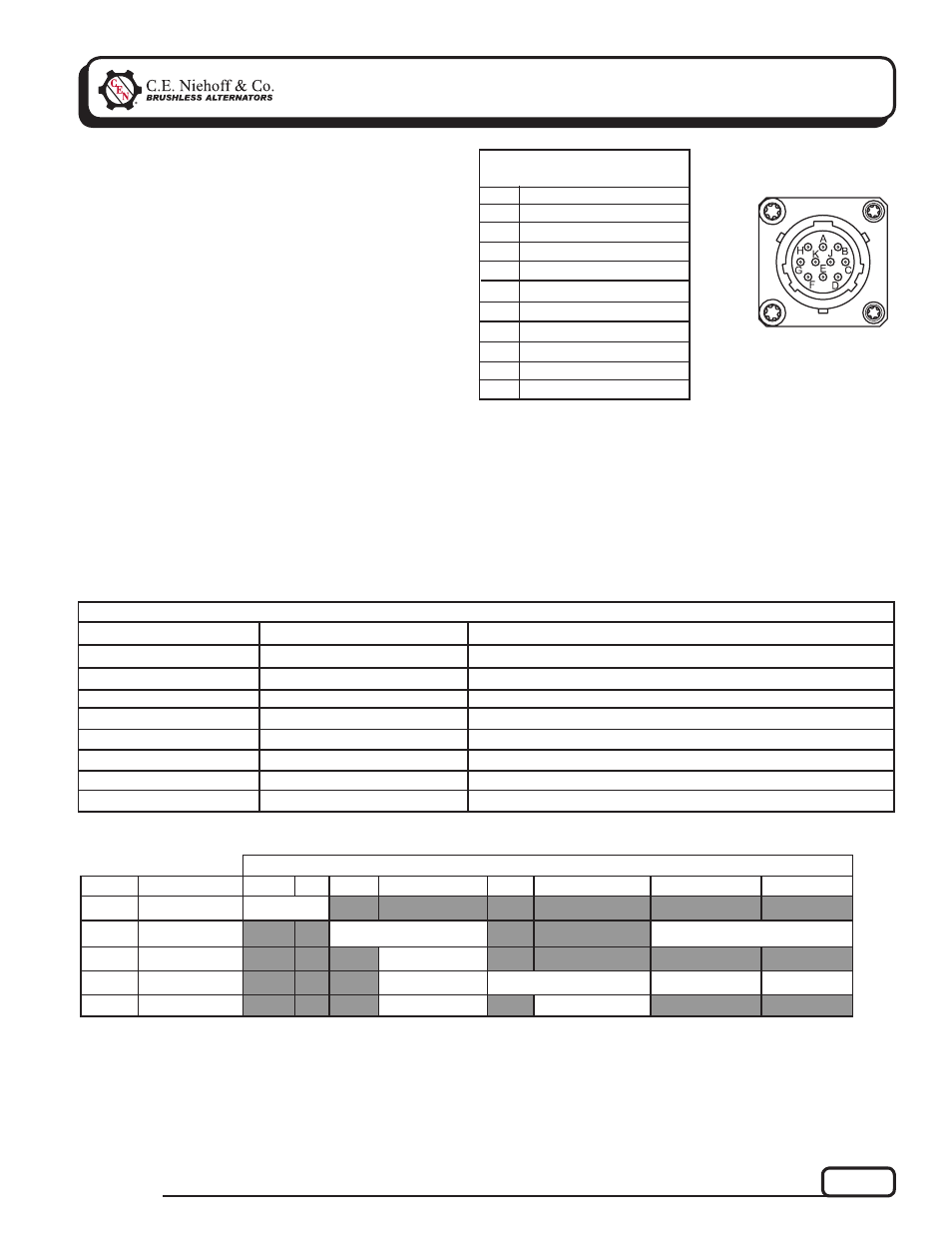
CEN uses MIL-C-26482 to interface between the N3234
and the vehicle J1939 databus and battery box sensors.
Mating connector is MS3116E12-10S or equivalent.
If this connection is not used, it must be sealed with
connector cover MS3181-12CA or equivalent. Connector
pinout is shown in Table 1. Message content is shown
in Table 2.
Battery box sensing inputs connect to battery pack
positive terminal (pin J) and battery box thermistor
(pin H). Thermistor is 10K NTC with 32650Ω at 0ºC,
10000Ω at 25ºC, 3601Ω at 50ºC and 1% interchange-
ability. Thermistor location should be chosen so that it
closely represents battery case temperature. Thermistor
connects between pin H and vehicle chassis, battery
pack negative terminal, or negative bus bar. If either
sensing input (pin H or J) is not used, regulator will
default to internal temperature and alternator voltage.
Pin
Identifi cation
TABLE 1 – J1939 Connector
Circuit Identifi cation
A
B
C
D
E
F
G
H
J
K
J1939+
J1939–
J1939/SHLD
B–/GND
Mfr use only
Mfr use only
Mfr use only
Ext. Temp. Sense
Ext. Voltage Sense
unused
Figure 3 – J1939
Connector Pins
Regulator Readout
Expected Reading
TABLE 2 – N3234 Regulator/J1939 Readout Diagnostics (see Table 3)
Action If Expected Reading Not Present
Alternator Speed
Alternator Voltage
Battery Voltage
Regulator Temp.
Alternator Current
Alternator Load
Battery Temp.
Stator Voltages
1500 to 8000 RPM
26 to 30 V (when charging)
26 to 30 V (when charging)
–40 to 125ºC
0 to 300 A
0 to 100%
–40 to 80ºC
10 to 18 V (when charging)
Check belts and pulley.
Check alternator drive and regulator IGN signal.
Check battery box voltage sense signal.
Check regulator.
Check alternator output cabling.
Check alternator output cabling.
Check battery box thermistor.
Check alternator belts and output.
Notes:
(1) Byte 1 broadcast closest to CAN frame ID.
Table 3 — Message Data
PGN
Name
1
(1)
2
3
4
5
6
7
8
FED5
Alt. Speed
Alt. RPM
FEF7
Alt. Voltage
Alt. Voltage
Batt. Voltage
FEA7
Alt. Temp.
Alt. Temp.
FFC8
Proprietary #1
Warning Light
Regulator Hrs.
Load
Batt. Temp.
FFC9
Proprietary #2
OVCO Count
Software Version