C.E. Niehoff & Co. N1335 Troubleshooting Guides User Manual
Page 2
Page 2
TG0052A
Section 1: Wiring Diagram
CEN N1335 Alternators
Description and Operation
N1335 28 V 300 A alternators are internally rectified.
All windings and current-conducting components are
non-moving, so there are no brushes or slip rings to
wear out.
After engine is running,
N3234 regulator receives ener-
gize signal. Regulator monitors alternator rotation and
provides field current only when it detects alternator
shaft rotating at or above idle speed.
After regulator detects alternator rotation, it gradually
applies field current, preventing an abrupt mechanical
load on accessory drive system. The soft start may take
up to 5 seconds.
N3234 regulator used with these units also
• is negative temperature compensated. Setpoint is
28.8 ± 0.5 V at 72 F when configured to operate with
6TMF type batteries.
• provides overvoltage cutout (OVCO). Regulator will
trip OVCO when system voltage rises above setpoint
by 3 V for longer than 3 seconds. OVCO feature
detects high voltage and reacts by opening alternator
field circuit and turning off alternator. Restarting
engine or waiting until system voltage drops 5 V
below setpoint will reset OVCO circuit.
• maintains alternator steady-state output voltage at
regulated settings as vehicle electrical loads are
switched on and off.
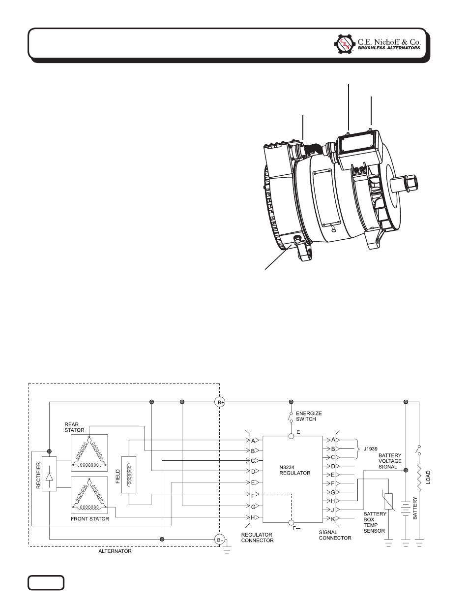
Figure 2 — N1335 Alternators with N3234 Regulator
Figure 1 — N1335 Alternator and
N3234 Regulator Terminals
B+ terminal
(next to regulator connector)
T
E terminal
B–
terminal
T
T
T
F- terminal