Can/j1939 interface – C.E. Niehoff & Co. N1224 Standard Troubleshooting Guides User Manual
Page 4
Page 4
TG0045A
Section 3: J1939 Operation Modes
CAN/J1939 Interface
DESCRIPTION AND OPERATION
The CEN N3221, N3229, and N3232 digital regulators
are compatible with SAE J1939 communications stan-
dard for vehicle networking.
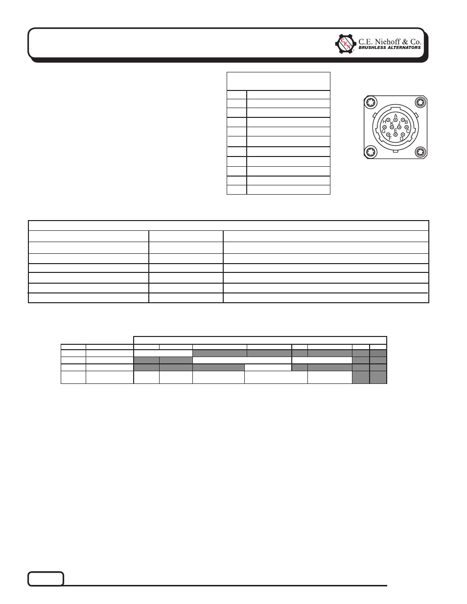
CEN uses MIL-STD connector MS3112E12-10P to inter-
face between the regulator and the vehicle J1939 data-
bus. Mating connector is MS3116E12-10S or equivalent.
If this connection is not used, it must be sealed with
connector cap and chain MS3181-12CA or equivalent-
supplied with all regulators. Connector pinout is shown
in Table 2. Message content is shown in Table 4.
Pin
Identifi cation
TABLE 2 – J1939 Connector
Circuit Identifi cation
A
B
C
D
E
F
G
H
J
K
J1939+
J1939–
J1939/SHLD
Mfr use only
Mfr use only
Mfr use only
Mfr use only
unused
unused
unused
Figure 3 – J1939
Connector Pins
Notes:
Unused bytes broadcast as 0xff.
Contact C.E. NIehoff & Co. for definition of custom proprietary message content.
Regulator Readout
Expected Reading
TABLE 3 – N3221/N3229/N3232 Regulator—J1939 Readout Diagnostics (see Table 4)
Alternator Output Voltage 28 V
Alternator Output Voltage 14 V
Alternator Speed
Regulator Temperature
Alternator Output
Charging System Hours
27–29 V
13.5–14.5 V
1200 to 8000 RPM
Less than 257 F/125ºC
0–100%
>0 hours
Action If Expected Reading Not Present
See Chart 1, page 6.
See Chart 1, page 6.
Check drive belt and charging system connections.
Decrease load on alternator.
Varies with load.
Check drive belt and charging system connections.
Table 4 — Message Data (Byte
1 Broadcast after Message ID)
PGN
Name
1
2
3
4
5
6
7
8
FED5
Alt. Speed
ALT RPM
FEF7
Alt. Voltage
24 V OUTPUT
12 V OUTPUT
FEA7
Temperature
REG TEMP
FFC8
Proprietary
#1
ALT
LOAD
STATUS
OVCO TRIP
COUNT
REG HOUR
METER
REG MINS
(0-59)