Caution, Notice – C.E. Niehoff & Co. C802/C802D/C820 Troubleshooting Guides User Manual
Page 4
Page 4
TG0004E
Basic Troubleshooting
1.
Inspect charging system components for damage
Check connections at B– cable, B+ cable, and
regulator harness. Also check connections at
regulator terminal wiring from regulator to vehicle
components. Repair or replace any damaged
component before electrical troubleshooting.
2.
Inspect vehicle battery connections
Connections must be clean and tight.
3.
Check drive belt
Repair or replace as necessary.
4.
Determine battery voltage and state of charge
If batteries are discharged, recharge or replace
batteries as necessary. Electrical system cannot be
properly tested unless batteries are charged 95% or
higher.
5.
Connect meters to alternator
Connect red lead of DMM to alternator B+
terminal and black lead to alternator B– terminal.
Clamp inductive ammeter on B+ cable.
6.
Operate vehicle
Observe charge voltage.
If charge voltage is above
32 volts, immediately shut
down system. Electrical
system damage may occur if
charging system is allowed to
operate at high voltage.
Go to Table 1.
If voltage is at or below regulator setpoint, let
charging system operate for several minutes to
normalize operating temperature.
7.
Observe charge volts and amps
Charge voltage should increase and charge amps
should decrease. If charge voltage does not
increase within ten minutes, continue to next step.
8.
Battery is considered fully charged if charge
voltage is at regulator setpoint and charge amps
remain at lowest value for 10 minutes.
9.
If charging system is not performing properly,
go
to:
• C802 — Chart 2, page 7.
• C820 — Chart 4, page 9.
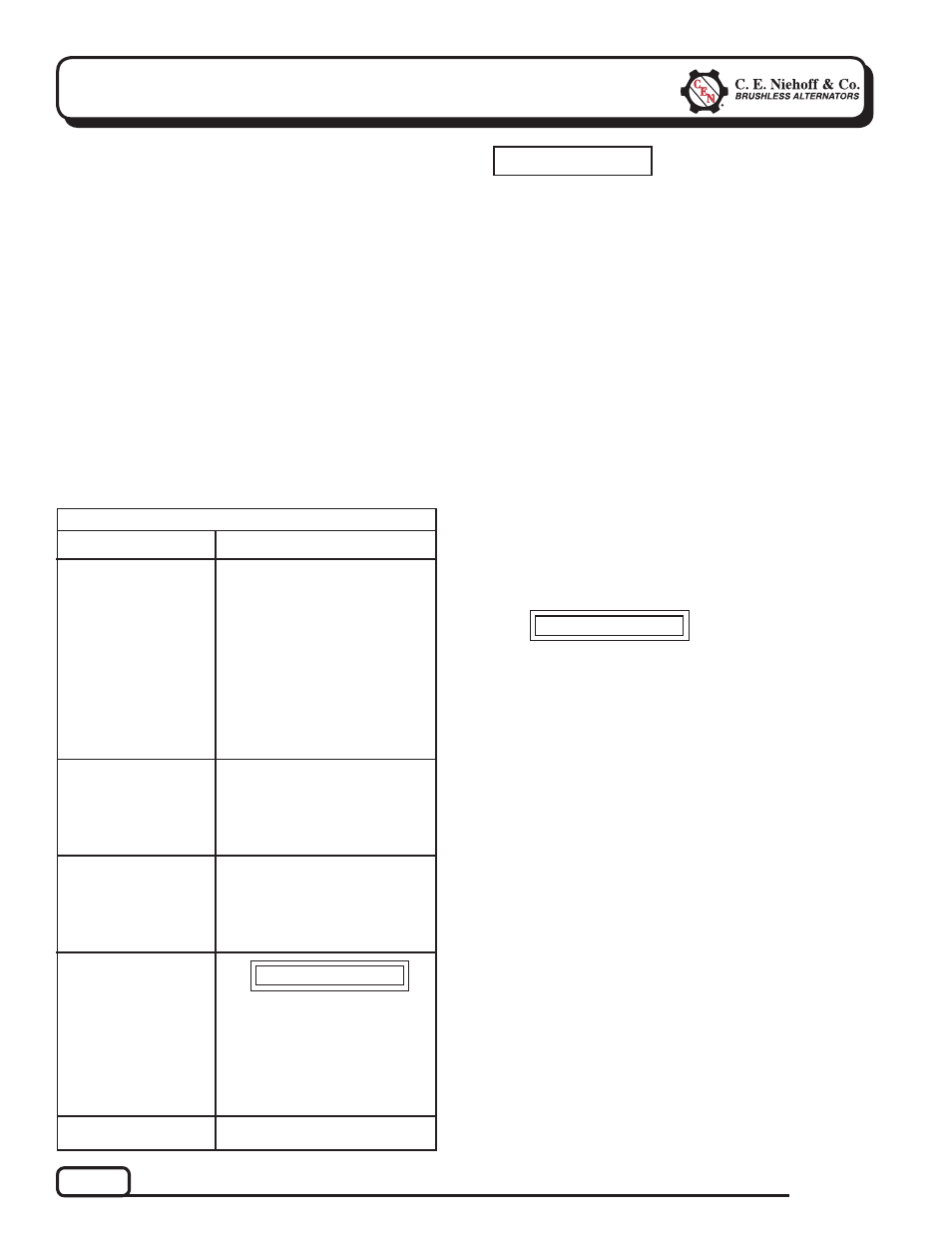
CAUTION
SYMPTOM
ACTION
TABLE 1 – System Conditions
Check: loose drive belt; low bat-
tery state of charge.
Check: current load on system
is greater than alternator can
produce.
Check: defective wiring or poor
ground path; low regulator
setpoint.
Check: defective or damaged
alternator and/or regulator.
Check: wrong regulator.
Check: high regulator setpoint.
Check: C802 only—OVCO
tripped.
Check: defective regulator.
Check: alternator.
Check: broken drive belt.
Check: battery voltage at alter-
nator output terminal.
Check: defective alternator
and/or regulator.
If alternator warning light on
vehicle is ON, do not operate
vehicle until troubleshooting
resolves the condition.
Check: defective alternator or
regulator. Go to Chart 2,
page 7.
Check: defective regulator.
Go to Chart 5, page 10.
Low Voltage Output
High Voltage Output
No Voltage Output
Preliminary Check-out
Check symptoms in Table 1 and correct if necessary.
Tools and Equipment for Job
• Digital Multimeter (DMM)
• Ammeter (digital, inductive)
• CEN Regulator Bypass Adapter A10-129
• Jumper wire
Identifi cation Record
List the following for proper troubleshooting:
Alternator model number _________________________
Regulator model number ________________________
Setpoints listed on regulator _____________________
T
T
T
No Air-Conditioning/
Alt. Warning Light On
(C802 only)
No 14 V Output
(C820 only)
Section B: Basic Troubleshooting
CAUTION
Failure to check for the following
conditions will result in erroneous
test results in the troubleshooting
charts.
NOTICE