C.E. Niehoff & Co. C802/C802D/C820 Troubleshooting Guides User Manual
Page 2
Page 2
TG0004E
Section A: Wiring Diagram
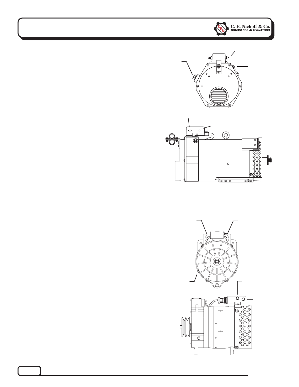
CEN C820 Alternator
Description and Operation
C820 28 V/14 V, 150 A/150 A alternator is internally
rectified. All windings and current-transmitting
components are non-moving, so there are no brushes
or slip rings to wear out. Energize switch activates
regulator. Field coil then ramps up to full power within
30 seconds (as a function of the regulator). Upper voltage
(28 V) is rectified with standard diodes. Lower voltage
(14 V) circuit output current is controlled by SCRs in
the drive end housing.
A2-303 regulator furnished with this unit maintains
alternator output voltage at regulated setting as vehicle
electrical loads are switched on and off. Alternator
output current is self-limiting and will not exceed
rated capacity of alternator.
CEN C802, C802D, and C802TD Alternators
Description and Operation
C802, C802D, and C802TD 28 V, 450 A alternators are
internally rectified. All windings and current-transmitting
components are non-moving, so there are no brushes or
slip rings to wear out. Energize switch activates regulator.
Field coil is then energized. Regulator maintains alterna-
tor output voltage at regulated setting as vehicle electrical
loads are switched on and off. Alternator output current
is self-limiting and will not exceed rated capacity of alter-
nator.
A2-213 regulator furnished with these units has a D+
terminal that can provide signal to vehicle electrical
system, confirming alternator operation. Regulator also
provide overvoltage cutout (OVCO). Regulator also has a
P terminal that can provide an optional AC voltage tap
and an IGN terminal. See page 5 for description and
operation of LED on this regulator.
B– Terminal
B+ Terminal
D+ Terminal
IGN Terminal
IGN
Terminal
F– Sense
Terminal
(Optional)
Figure 1 — C802/C802D/C802TD
Figure 2 — C820
B– Terminal
(either side)
14 V
B+ Terminal
28 V
B+ Terminal
T
T
T
T
T
T
T
T
T
P Terminal
T