C.E. Niehoff & Co. C726 Troubleshooting Guides User Manual
Page 2
Page 2
TG69A
Section A: Wiring Diagram
CEN C726 Alternator
Description and Operation
C726 42 V 380 A alternator is internally rectified. All
windings and current-conducting components are
non-moving, so there are no brushes or slip rings to
wear out.
After engine is running,
A2-339 regulator receives
energize signal. Regulator monitors alternator rota-
tion and provides field current only when it detects
alternator shaft rotating at or above idle speed.
After regulator detects alternator rotation, it gradual-
ly applies field current, preventing an abrupt me-
chanical load on accessory drive system. The soft
start may take up to 20 seconds.
A2-339 regulator used with these units also
• is negative temperature compensated. Setpoint is
42.0 V at 72 F.
• provides overvoltage cutout (OVCO). Regulator
will trip OVCO when system voltage rises above
46 volts for longer than 3 seconds. OVCO feature
detects high voltage and reacts by opening alter-
nator field circuit and turning off alternator.
Removing and reapplying energize signal at IGN
terminal will reset OVCO circuit.
• maintains alternator steady-state output voltage
at regulated settings as vehicle electrical loads are
switched on and off.
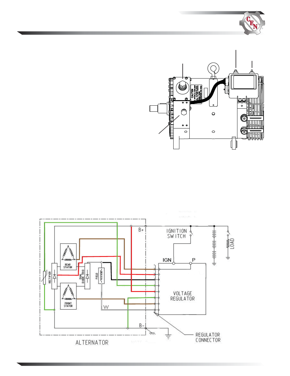
Figure 2 — Wiring Diagram
Figure 1 — C726 Alternator and
A2-339 Regulator Terminals
B+ terminal
IGN terminal
B–
terminal
P terminal
BR
R
BK
G
R
W
G
BR
A
B
C
D
E
F
G
H