C.E. Niehoff & Co. C651/C654 Troubleshooting Guides User Manual
Page 5
Page 5
TG0010C
S
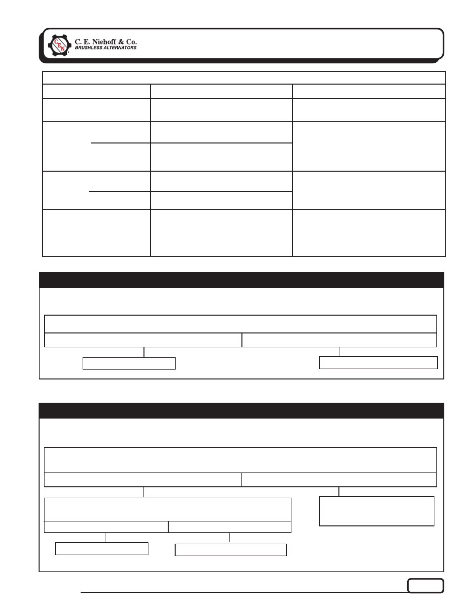
ection 3: Advanced Troubleshooting
(CONT’D)
Yes
No
System is overloaded. Check for
excessive draw from
accessories.
With engine running, measure voltage at low battery B+ terminal. See
➀
in Figure 3 on page 4.
Is voltage equal to regulator set point or no more than 1 V below set point?
Chart 2 – RED LED On Steady – No Alternator Output – Test OVCO Circuit
Yes
No
Replace existing regulator with known good regulator. Run engine.
Does OVCO trip?
Alternator is defective.
Original regulator is defective.
T
T
T
T
T
T
T
T
T
T
T
T
T
T
T
T
T
T
T
T
Yes
No
Original regulator is defective.
Replace regulator with known good regulator. Run engine. Does OVCO trip?
Chart 1 – AMBER LED On Steady – No Alternator Output – Test OVCO Circuit
Alternator is defective.
T
T
T
T
T
T
T
T
T
T
Make sure batteries are properly charged before proceeding.
Make sure batteries are properly charged before proceeding.
LED COLOR
STATUS
TABLE 2 – A2-306 Regulator Diagnostics
Alternator and regulator operating normally.
GREEN
Flashing
(key on, engine running)
ACTION
No action required.
See Chart 1 below.
AMBER
Steady
(key on, engine off)
Flashing
High or low battery tripped OVCO.
See Chart 2 below.
RED
Steady
(key on, engine off)
Flashing
Flashing both
colors
Low battery amp draw exceeds 125 amps.
Low battery tripped OVCO.
Alternator not rotating or 14 V output
voltage unstable.
1.
Check battery, system cable connections
and grounds.
2.
Perform load analysis.
3.
If OK, replace alternator.
GREEN/
AMBER
28 V output voltage unstable.