A2-306 regulator, Notice c b a – C.E. Niehoff & Co. C651/C654 Troubleshooting Guides User Manual
Page 4
Page 4
TG0010C
A2-306 Regulator
DESCRIPTION AND OPERATION
A2-306 Regulator with OVCO is attached directly
to the outside of alternator.
Main diagnostic feature of A2-306 regulator is
tricolored (red, amber, green) LED next to harness
receptacle on regulator. LED works like a voltmeter,
measuring charging voltage. See Table 2 on page 5
for diagnostic features and LED explanations.
Regulator with OVCO (overvoltage cutout) will trip
at one of the following conditions:
•
Voltage higher than regulator setpoint that exists
longer than 3 seconds at low battery. OVCO
feature detects high voltage and reacts by signal-
ing relay in F+ alternator circuit to open. This
turns off alternator (LED is steady AMBER light).
Restarting engine resets OVCO circuit. Regulator
regains control of alternator output voltage.
•
Voltage lower than regulator setpoint that exists
longer than 3 seconds at low battery. OVCO
feature detects low voltage and reacts by signaling
relay in F+ alternator circuit to open. This turns
off alternator (LED is steady RED light). Restarting
engine resets OVCO circuit. Regulator regains
control of alternator output voltage.
•
Voltage higher than regulator setpoint that exists
longer than 3 seconds at high battery. OVCO
feature detects high voltage and reacts by signal-
ing relay in F+ alternator circuit to open. This
turns off alternator (LED is steady RED light).
Restarting engine resets OVCO circuit. Regulator
regains control of alternator output voltage.
TROUBLESHOOTING
Before troubleshooting, make sure batteries are
connected in series, not parallel circuits. See Figures
2 and 3 for connections.
Shut down vehicle and restart engine. If alternator
functions normally after restart, a “no output condi-
tion” was normal response of voltage regulator to
“high voltage” condition. Inspect condition of electrical
system, including loose battery cables, both positive
and negative. If battery disconnects from system, it
could cause “high voltage” condition in electrical
system, causing OVCO circuit to trip.
If you have reset alternator once, and electrical
system returns to normal charge voltage condition,
there may have been a one time, high voltage spike,
causing OVCO circuit to trip.
If OVCO circuit repeats cutout a second time in short
succession and shuts off alternator F+ circuit, try
third restart. If OVCO circuit repeats cutout a third
time, check color of LED while engine is running.
AMBER LED - go to Chart 1, page 5.
RED LED - go to Chart 2, page 5.
Listed regulator setpoints:
Position #1 - 27.5 V
± 0.2 V
/13.8 V
± 0.1 V
Position #2 - 28.0 V
± 0.2 V
/14.0 V
± 0.1 V
Position #3 - 28.5 V
± 0.2 V
/14.2 V
± 0.1 V
Position #4 - 29.0 V
± 0.2 V
/14.5 V
± 0.1 V
Section 3: Advanced Troubleshooting
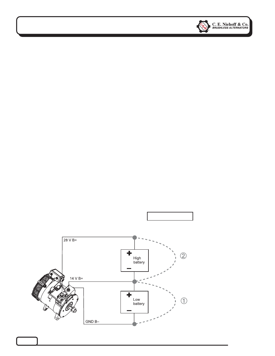
Figure 3 – Meter Placement
Meter placement for
high battery reading
Meter placement for
low battery reading
Measurement from A to C
is not used by regulator to
control voltage. Regulator measures A to B and B to C
separately.
NOTICE
C
B
A