Caution – C.E. Niehoff & Co. C651/C654 Troubleshooting Guides User Manual
Page 2
Page 2
TG0010C
Section 1: Wiring Diagram
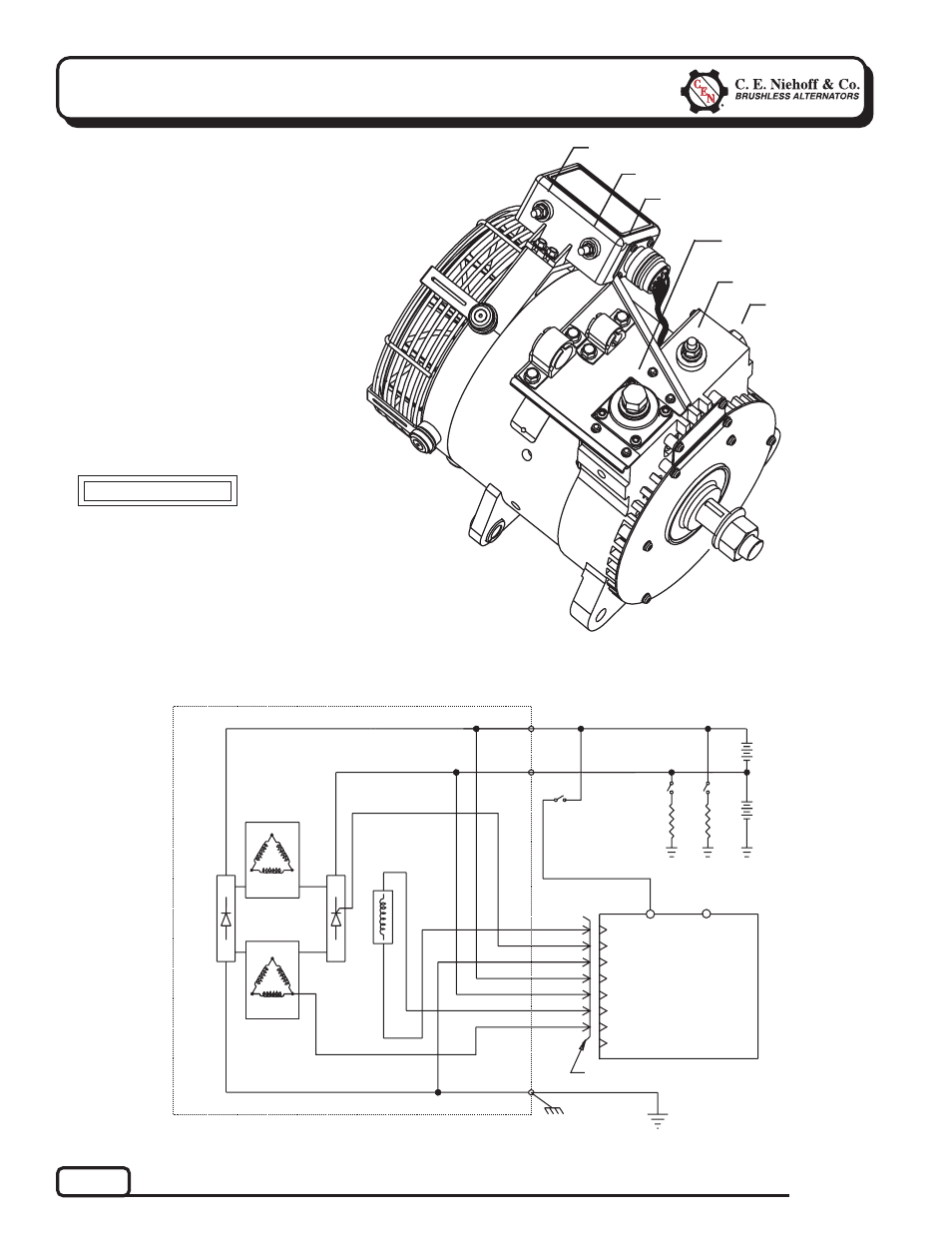
CEN C651 and C654 Alternators
Description and Operation
C651 28 V (240 A)/14 V (100 A) and C654 28 V
(260 A) /14 V (100 A) alternators are internally
rectified. All windings and current-transmitting
components are non-moving, so there are no
brushes or slip rings to wear out. Energize
switch activates regulator. Regulator cycles
field coil off and on until system voltage is
is reached. Upper voltage (28 V) is rectified
with standard diodes. Lower voltage (14 V)
circuit output current is controlled by
SCRs in the drive end housing. Alternator
output current is self-limiting and will
not exceed rated capacity of alternator.
A2-306 regulator used with these units:
•
is for use with batteries connected in
series, not parallel.
Regulator is designed to
control system through
series not parallel circuits. See Figures 2 and 3 for connections.
•
maintains alternator output voltage at regulated
setting as vehicle electrical loads are switched
on and off.
•
monitors low and high batteries in system separately.
•
limits 14 V alternator output current to 100 A. 14 V
source from R terminal on regulator is limited to 1 A
when alternator is rotating.
B– Terminal
R Terminal
E Terminal
Figure 2 — C651 and C654 Alternator with Regulator
Figure 1 — C651 and C654 Alternator Terminals
14 V B+ Terminal
28 V B+ Terminal
T
T
T
T
T
T
T
T
T
T
T T T T T
T
T
T
T
T
T
T
T
T
T
B+
28 V
14 V
B–
RECTIFIER
SCR
GA
TE
FIELD
REGULATOR
REGULATOR RECEPTACLE
ALTERNATOR
14
V
LOAD
28
V
LOAD
BA
TTER
Y
STATOR
STATOR
ENERGIZE
SWITCH
E
E
D
C
B
A
BA
TTER
Y
H (unused)
G
F
R
Tricolor (R, A, G) diagnostic LED
T
T
T
T
T
T
T
T
T
T
CAUTION