C.E. Niehoff & Co. C629 Troubleshooting Guides User Manual
Page 4
Page 4
TG72A
Section B: On-Vehicle Troubleshooting
(CONT’D)
If you have questions about your alternator or any of these test procedures, or if you need to locate a Factory Authorized Service Dealer, please contact us at:
C.E. Niehoff & Co.• 2021 Lee Street • Evanston, IL 60202 USA
TEL: 800.643.4633 USA and Canada • TEL: 847.866.6030 outside USA and Canada • FAX: 847.492.1242
E-mail us at [email protected]
No Alternator Output – Test Charging Circuit
• BEFORE STARTING DIAGNOSTIC SEQUENCE, VERIFY THE FOLLOWING AND REPAIR/REPLACE IF NOT
TO SPEC:
—BATTERIES FOR STATE-OF-CHARGE (24.5-25.5 V), CONDITION, AND SECURE CONNECTIONS
—MASTER BATTERY SWITCH FOR FUNCTION
MASTER BATTERY SWITCH ON, KEY ON, ENGINE ON: Test for battery voltage at B+ terminal on alternator
to ground, then at IGN terminal on regulator to ground.
Yes
No
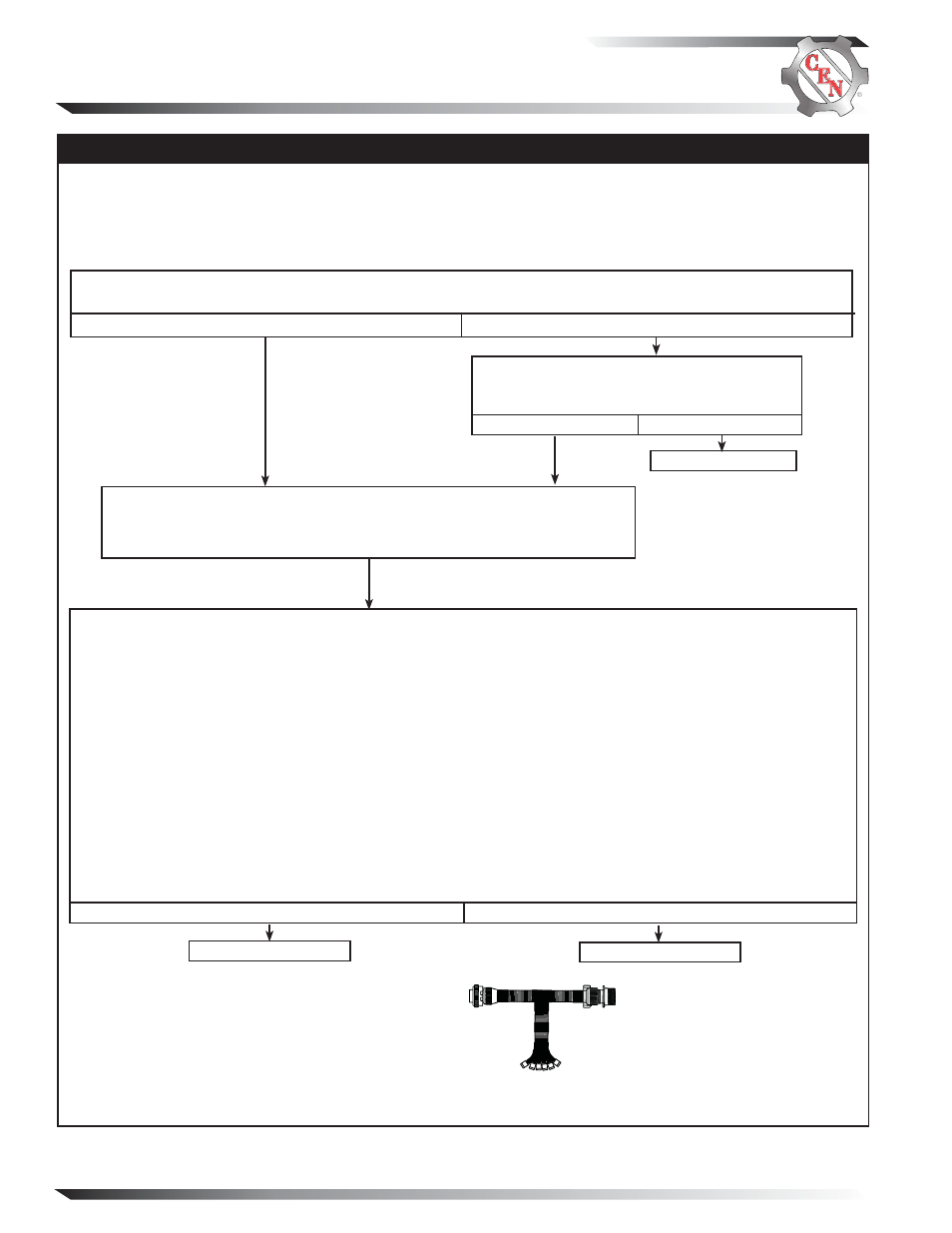
Figure 5 – CEN 6-pin A10-114 Inline Harness Tool
Socket Connections
SOCKET CONNECTIONS
Socket A Not used
Socket B Phase
Socket C B –
Socket D B+
Socket E D+
Socket F F+
MASTER BATTERY SWITCH ON, KEY OFF, ENGINE OFF: Readings of all five tests must pass.
1. Battery voltage test: Connect DMM red lead to socket D in test tool. Connect DMM black lead to socket C in test
tool. Battery voltage should exist.
2. Field coil resistance test: Set DMM to ohms test. Field resistance between socket F and C in test tool should mea-
sure nominal 1.0-1.5 ± 0.2 ohms. Field coil is defective if reading is less than 0.5 ohms or greater than 3 ohms.
3. Significant magnetism test:
a. Securely connect one end of a jumper wire to socket F in test tool.
b. Momentarily (1 sec.) touch other end of jumper wire to alternator B+ terminal. Spark will occur at B+ terminal.
Touch steel tool to shaft to detect significant magnetism.
4. Turn off master battery switch. Disconnect B+ battery cable on alternator. Set DMM to diode test. Connect black
lead on DMM to socket E in test tool and red lead to B+ terminal on alternator. DMM should read OL. Reverse
leads. DMM should read OL again. Reconnect B+ battery cable to alternator. Turn on master battery switch.
5. Phase taps test: Set DMM to diode test. Connect DMM black lead to socket B in test tool. Connect red lead to
alternator B+ terminal. DMM should read blocking in this direction. Then reverse leads. DMM should read flow
in this direction. Repeat for socket B and B– terminal. Tests should read flow in one direction and blocking in
the other direction.
Yes
No
Alternator is defective.
ENGINE OFF: Disconnect 6-pin alternator-to-regulator harness plug at
regulator and connect CEN A10-114 inline test tool to harness plug end only.
Make sure connections are secure.
Regulator is defective.
Repair vehicle wiring as necessary. Run engine
and re-test charging circuit. Is charging system
performing properly?
System is operative.
No
Yes
A B C D E F