C.E. Niehoff & Co. C629 Troubleshooting Guides User Manual
Page 2
Page 2
TG72A
Section A: Alternator and Regulator
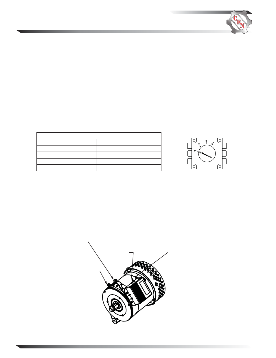
Figure 3—Alternator with A2-216 Regulator
IGN terminal
B+ Terminal
D+ Terminal
B
− Terminal
Figure 2—Voltage Setpoints
Table 1— Voltage Setpoint Switch Position
Voltage Setpoints (±0.2 V)
Battery Type*
Position 1
27.5 V
Maintenance
Position 2
28.0 V
Maintenance
Position 3
28.5 V
Maintenance-free
Position 4
29.0 V
Maintenance-free
* Setpoint can depend on temperature or climate condition, as well as
battery type. If boiling or excessive gassing occurs with higher voltage
setpoint, change to next lower voltage setpoint.
CEN C629 Alternator/Regulator Description and Operation
C629 28 V (260 A) alternator is internally rectified. All windings and current-transmitting components are non-moving,
so there are no brushes or slip rings to wear out.
This alternator is externally energized when the battery master switch on the vehicle is turned on and provides
power to the regulator through the IGN circuit.
Field coil is then energized. AC is rectified into DC output through diodes in drive end rectifier housing and supplied
to the battery from the alternator B+ terminal. See schematic diagram on page 3. Alternator output current is self-limit-
ing and will not exceed rated capacity of alternator. Regulator maintains alternator output voltage at pre-determined
regulated setting (see Table 1 below for setpoints) as vehicle electrical loads are switched on and off.
Battery type selection and battery maintenance/function are the sole responsibilities of the customer.
A2-216 regulator furnished with some units include:
• External IGN terminal for energize connection.
• D+ terminal that can provide DC voltage signal to vehicle electrical system, confirming alternator operation.
• Overvoltage cutout (OVCO) function. See page 3.
• Green-lensed LED. See page 3.
• Regulator fixed (flat temperature compensation) setpoints shown in Table 1 are selected based on battery type.