C.E. Niehoff & Co. C510/C540 Troubleshooting Guides User Manual
Page 6
Page 6
TG1B
Section D: Advanced Troubleshooting
(CONT’D)
Chart 2 – Low Voltage Output – Alternator Not Keeping Up with Load (cont’d)
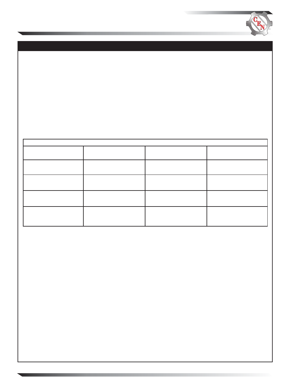
RECTIFIER TEST
The following will test modules inside rectifier:
1.
Disconnect all battery cables.
2.
Disconnect harness leads to rectifier terminals P1, P2 and P3.
3.
Disconnect B+ and B– cables from rectifier.
4.
Unplug rectifier-to-regulator harness.
5.
Unplug alternator field circuit harness connector.
6.
Use DMM set to diode tester. Meter readings should not vary more than 10%, test to test.
7.
If expected reading is not obtained, diode inside module is most likely defective. Diode modules are
individually replaceable. Consult CEN authorized service distributor for more information.
8.
If tests indicate rectifier is good, alternator is defective. Consult CEN authorized service distributor
for more information.
Negative (Black)
Meter Lead on
TABLE 2 – Diode Test
B+ terminal on rectifier.
Correct Result
on Meter
What You
Are Measuring
Uniform voltage drop
across each positive diode.
Positive side diode is
conducting.
P1, P2, P3 terminals on
rectifier, one at a time.
DMM will read OL
(out of limits).
Positive side diode is
blocking.
B– terminal on rectifier.
Uniform voltage drop
across each negative
diode.
Negative side diode is
blocking.
P1, P2, P3 terminals on
rectifier, one at a time.
DMM will read OL
(out of limits).
Negative side diode is
conducting.
Positive (Red)
Meter Lead on
P1, P2, P3 terminals on
rectifier, one at a time.
B+ terminal on rectifier.
P1, P2, P3 terminals on
rectifier, one at a time.
B– terminal on rectifier.