C.E. Niehoff & Co. C510/C540 Troubleshooting Guides User Manual
Page 5
Page 5
TG1B
Section D: Advanced Troubleshooting
Yes
No
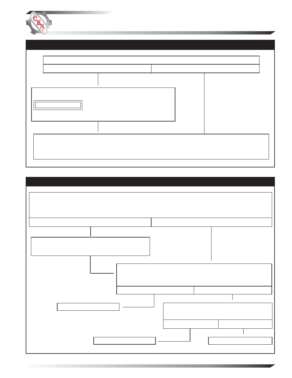
For “low voltage output” condition: go to Chart 2 below.
For “no voltage output” condition: go to Chart 3, page 7.
Is there a battery isolator in the system?
Chart 1 – System Circuit
Install temporary jumper between one battery terminal and alterna-
tor terminal on isolator. Use minimum 12 AWG wire.
Do not operate charging system more than two
minutes with jumper installed. Charging system
voltage will be abnormally high and damage other
components.
Yes
No
Inspect harnesses and connections for corrosion.
Repair/replace as necessary. Repeat test.
Voltage value should be less than 0.1 V.
Operate engine at idle, battery as sole load, no other loads applied. Measure charge voltage at battery posts
(B+ to B-) and output voltage at rectifier B+ and B– terminals. Measure charge amps entering battery and charge
amps out of alternator at rectifier B+ terminal.
Is difference in voltages greater than 0.2 V and amp difference less than 20 A?
Chart 2 – Low Voltage Output – Alternator Not Keeping Up with Load
Yes
No
Increase engine speed to 1200 rpm, battery as sole load, no other loads
applied, meters attached as in box above. Increase load to 75, 150 and
280 A.
Does voltage remain steady?
Measure AC voltage from terminals: P1 to P2, P2 to
P3, and P3 to P1 on rectifier.
Are voltages within 5% of each other?
Re-test charging system.
START HERE
Yes
No
Start test at top of page 6.
Re-test charging system.
CAUTION