C.E. Niehoff & Co. C510/C540 Troubleshooting Guides User Manual
Page 2
Page 2
TG1B
Section A: C510 Wiring Diagrams
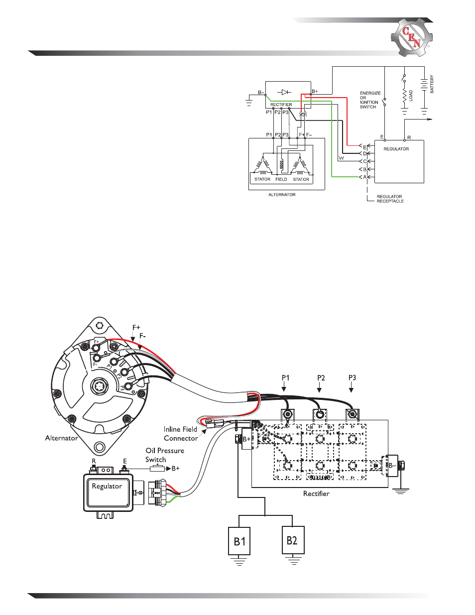
CEN C510 Alternator
Description and Operation
C510 14 V (280 A) 3-phase brushless alternator uses an
externally mounted rectifier and regulator. All windings
and current-transmitting components are non-moving,
so there are no brushes or slip rings to wear out. This
unit is externally energized through an energize switch,
which activates regulator. Field coil is then energized.
Regulator maintains alternator output voltage at regu-
lated setting as vehicle electrical loads are switched on
and off. Alternator output current is self-limiting and
will not exceed rated capacity of alternator.
A2-136 external regulator furnished with all units has
R terminal for optional AC voltage tap. Optional 15.5 V
regulator setpoint is available for battery isolator appli-
cations.
A8-201 or A8-205 external rectifier allows for mount-
ing in engine compartment. A8-205 rectifier suppresses
electromagnetic interference (EMI) with internal filters
to acceptable levels defined by the Society of Automotive
Engineers (SAE) specification J1113/41. A8-205 rectifier
will not reduce EMI from sources such as antennas,
poor cable routing practice, or other electronic devices
that cause EMI. If EMI continues, consult an electro-
magnetic compliance (EMC) specialist to determine EMI
source.
Figure 2 — C510 Terminal Locations
Figure 1 — C510 Wiring Diagram
BK
R
G
W