C181-1 alternator, W/ a8-208 rectifi er-regulator – C.E. Niehoff & Co. C180etc and C181etc Installation User Manual
Page 4
C181-1 Alternator
w/ A8-208 Rectifi er-Regulator
C. E. Niehoff & Co. • 2021 Lee Street • Evanston, IL 60202 Tech Services Hotline 800-643-4633
II162A
Page 4 of 4
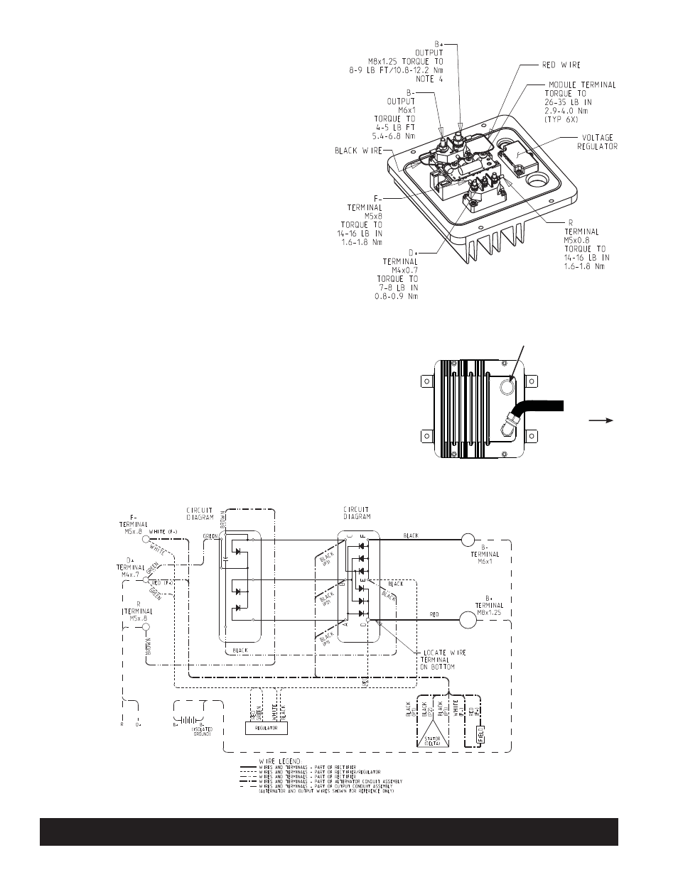
1. Install rectifier-regulator assembly in location
determined by customer, using hardware and
torque specified by customer.
2. Remove shipping spacers from both sides of
rectifier-regulator.
3. Connect rectifier-regulator to alternator
with wiring conduit shown in
Figure 7 and 8.
4. Output conduit supplied by customer
connects rectifier-regulator with
customer circuit and consists of
B+ and B– output leads plus
R and D+ terminal leads if used.
5. R circuit current: 3 A max
Square wave signal: 0-30 V
Alternator speed formula: RPM=f(Hz)•10
6. Alternator is configured for self-
energization.
7. D+ terminal is the charge warning
lamp (CWL) connection.
8. Series connected isolation diode in the
B+ circuit is not permissible.
9. When wiring inside rectifier-regulator cover is
complete, re-install cover and torque hardware
to 5.4 Nm/48 lb. in.
Figure 7 - A8-208 Rectifier-Regulator Cover Connections
Figure 8 - C181-1/A2-208 Component Interconnection Diagram
To alternator
See step 2. M25 x 1.25 pipe thread for
connecting output conduit assembly