Main engine sensors, Optional sensors, 6 overview – MoTeC M8 User Manual
Page 8
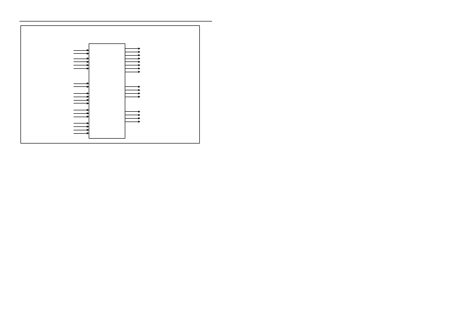
6 Overview
ECU
Fuel Injectors
Auxiliary Outputs
Ignition Outputs
Main Engine Sensors
INPUTS
OUTPUTS
eg. Idle Speed Valve
eg. Waste Gate Valve
Throttle Position
Engine Temp
Trigger Sensors
eg. Fuel Pump Relay etc
REF
Injector 1
TP
MAP
ET
AT
FP
Dig Input 1
Dig Input 2
EMAP
Lambda 1
SYNC
IGN 1
PWM1
PWM2
SW1
Injector 2
Injector 3
Injector 4
Injector 5
Injector 6
Injector 7
Injector 8
Inlet Air Temp
Manifold Pressure
Exhaust Manifold Pressure
Wide Band Mixture Sensors
Wheel Speed or Switch
Wheel Speed or Switch
Optional Sensors
Fuel Pressure
M8
Lambda 2
Dig Input 3
Dig Input 4
Wheel Speed or Switch
Wheel Speed or Switch
FT
Aux Temp 1
Fuel Temp
eg. Intercooler Temp
Aux Temp 2
Aux Temp 3
eg. Exhaust Gas Temp
eg. Gear Box Temp
Aux Temp 4
eg. Diff Temp
SW2
IGN 2
IGN 3
IGN 4
Ignition 1 (Shared with Dig Input 4)
Ignition 3 (Shared with Dig Input 2)
Ignition 4 (Shared with Dig Input 1)
Ignition 2 (Shared with Dig Input 3)
Main Engine Sensors
The Main Engine Sensors are required for correct operation of the ECU.
The engine RPM is derived from the REF trigger sensor.
The SYNC trigger sensor is required for Sequential Injection or Multi Coil
Ignition Systems.
The Throttle Position, Manifold Pressure, Air Temp and Engine Temp are
used as inputs to the various calibration tables.
Optional Sensors
The Optional Sensors are not required for basic operation of the ECU.
The Digital Inputs may be used for wheel speed measurement or to activate
functions such as Dual RPM Limit, or Nitrous. (Advanced Tuning Only)
The Lambda Inputs may be used for wide band air fuel ratio measurement or
wide band or narrow band closed loop lambda control.
The other inputs may be used for data logging or for special calibration
features.