Ec mot, M48 ecu wiring, Sensors injectors – MoTeC M8 User Manual
Page 58
56
eC
MoT
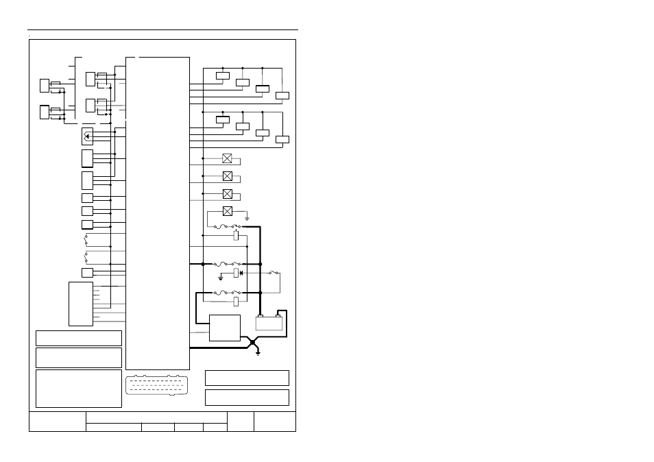
M48 ECU Wiring
Date
Drawn
Rev
15 / 1 / 1995
TW
A
Drawing No
ECU
App
Title
REF Hall
REF Mag
6
5
ECU
Ref
(Hall or Optical)
5V
(Manifold Pressure)
(Optional)
MAP
1
12
13
25
24
36
Sensors
Injectors
25
Injector 1
GND
26
+
Sig
-
8V
SYNC Hall
SYNC Mag
8
7
Sync
(Hall or Optical)
+
Sig
-
5
26
8
7
+
-
+
-
(Magnetic)
Ref
(Magnetic)
Sync
4
16
C
B
A
17
MAP
(Auxiliary Voltage)
AUX V
18
(Throttle Position)
TP
Aux Volt
TP
Open
Closed
28
(Air Temp)
AT
AT
29
(Engine Temp)
ET
ET
31
(Lambda Sensor)
LA
LA +
27
0V
32
(Optional)
Digital 1
(Optional)
19
Dig Input 1
Injector 4
2
Injector 5
Injector 8
15
10
23
1st
2nd
3rd
4th
5th
6th
7th
8th
Connect in Firing Sequence
for Sequential Operation
Ignition
Switch
+
-
Battery
Fuse 20 A
Relay 30A
Relay 30A
Fuse 20 A
1
Bat +
Ignition
System
Earth at
Engine Block
Chasis
(See Detailed
Drawings)
30
Aux Temp
LA -
33
IGN1
AUX 1 13
AUX 2 / IGN 2 34
36
6
(Optional)
(Auxiliary Temp)
AUX T
20
Dig Input 2
Digital 2
(Optional)
24
11
12
9
1
3
5
2
8
4
7
9
6
PC Connector
D9 Male
35
(Aux Valve or Relay)
Fuse 20 A
(Aux Valve or Relay)
(Aux Valve or Relay)
Fuel Pump
AUX 3
AUX 4
Relay 30A
Note 1
The Fuse is essential to ensure that the ECU
is not damaged by reversed battery polarity
Note 2
To avoid the fuse blowing due to reverse
battery polarity use a diode activated relay
eg. Bosch 0 332 014 112
Note 3
The Ignition System Relay should be activated
using the Fuel Pump control wire to ensure
that the Ignition System is off when the engine
is stopped. Or use the Fuel pump relay to
to the Ignition System.
Note 4
The AUX1 Output can sink a maximum
current of 4 Amps.
The AUX2, AUX3, AUX4 Outputs can sink
a maximum current of 0.6 Amps.
Refer to the
Trigger Drawings
for details
Note 1
Note 2
Note 3
Note 4
Note 5
Note 5
Note 5
Note 5
This also provides reverse battery protection
power the Ignition System.
Sheet No
M48
Injector 6
21
Injector 7
22
Injector 2
3
Injector 3
14