Ec mot, Motec 57, M8 ecu wiring – MoTeC M8 User Manual
Page 59: Sensors injectors
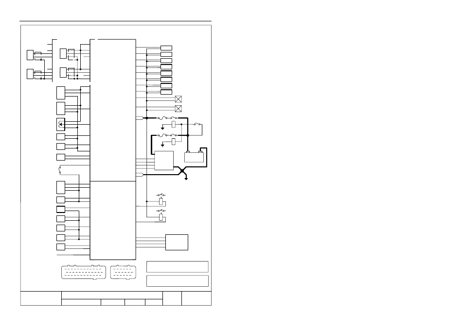
MoTeC
57
Ref+
Ref -
35A
33A
34A
ECU
Ref
(Hall or Optical)
5V
(Manifold Pressure)
(Optional)
MAP
1
12
13
25
24
36
Sensors
Injectors
1A
13A
Injector 1
GND
C
B
A
11A
+
Sig
-
8V
Ref PU
Sync+
Sync -
32A
30A
31A
Sync
(Hall or Optical)
+
Sig
-
Sync PU
22A
0V
1
6
7
13
12
18
35
33
34
11
32
30
31
22
+
-
+
-
(Magnetic)
Ref
(Magnetic)
Sync
12A
28A
C
B
A
27A
MAP
(Exhaust Pressure)
EMAP
29A
(Throttle Position)
TP
EMAP
TP
Open
Closed
26A
(Air Temp)
AT
AT
25A
(Engine Temp)
ET
ET
24A
(Lambda Sensor) 1
LA1
LA1 +
10A
0V
36A
(Optional)
(Switch)
SW
(Optional)
23A
Switch Input
36 Way Connector
18 Way Connector
5A
Injector 2 6A
Injector 3 7A
Injector 4 8A
Injector 5 17A
Injector 6 18A
Injector 7 19A
Injector 8 20A
1st
2nd
3rd
4th
5th
6th
7th
8th
Connect in
Firing Sequence
Ignition
Switch
+
-
Battery
Fuse 20 A
Relay 30A
Relay 30A
Fuse 20 A
2A
14A
Bat +
Bat +
Ignition
System
Earth at
Engine Block
Chasis
(See Detailed
Drawings)
(Optional)
+
Sig
-
13B
(Fuel Pressure)
FP
FP
8B
Aux Temp 1
Aux Temp 1
9B
Aux Temp 2
Aux Temp 2
7B
(Fuel Temp)
FT
FT
Aux Temp 3
Aux Temp 4
14B
Aux Temp 3
15B
Aux Temp 4
1B
5V
0V
3B
2B
0V
GND
4B
(Lambda Sensor 2)
LA2
LA2 +
10B
(Optional)
Knock
16B
Knock
(Optional)
(Optional)
(Optional)
(Optional)
(Optional)
LA1 -
LA2 -
3A
Dig In 4 / IGN1
4A
Dig In 3 / IGN2
Dig In 2 / IGN3
Dig In 1 / IGN4
15A
16A
PWM Output 1
9A
PWM Output 2
21A
(Control Valve)
(Optional)
(Control Valve)
(Optional)
(Optional)
Switched Output 1
5B
Switched Output 2
6B
(Aux Relay)
(Optional)
(Aux Relay)
(Optional)
STEP 1
18B
STEP 2
17B
STEP 3
12B
STEP 4
11B
Stepper Motor
(Optional)
Note 1
The PWM1, and PWM2 Outputs can sink a
maximum current of 4 Amps.
The Switched Output 1 and Switched Ouput 2
can sink a maximum current of 2 Amps.
Note 2
Note 2
Note 2
Note 1
Note 1
A
B
See the
Trigger Drawings
for details
eC
MoT
M8 ECU Wiring
Date
Drawn
Rev
17 / 1 / 1994
TW
B
Drawing No
ECU
App
Title
Sheet No
M8