Wiring diagram – Bray 52 Series User Manual
Page 14
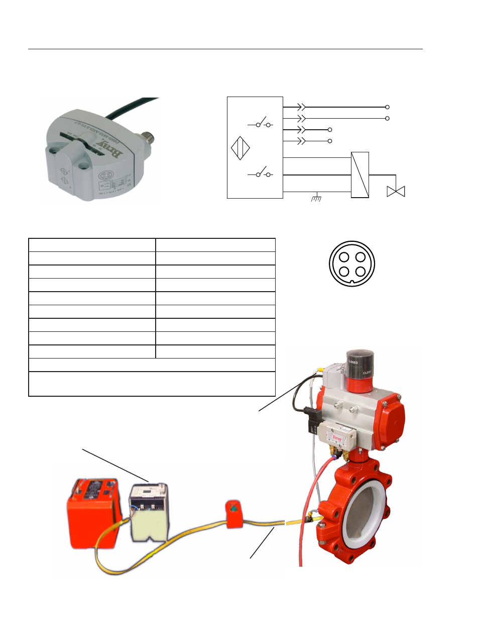
BRAY Series 52 Valve Status Monitor
Operation and Maintenance Manual
12
AS-i (Actuator Sensor Interface) Version with
M12 Quick Connector
Specifications:
Operating Voltage
30.5 VDC by AS-i Network
Target Type
Magnetic
Electrical Configuration
AS-i Spec. 3.2 (1), (2)
Maximum Switching Current
100mA
Consumption Current
< 25mA
Addressing
0 to 31A or B
Data Bits
Bit 0: Sensor 1
Bit 1: Sensor 2
Bit 2: Output to Solenoid
(1) Hardware AS-i Version 3.0 - configured as AS-i Version 2.1
(2) Full backwards compatibility is maintained with earlier
AS-i networks and products
M12 X1
CONNECTOR
PINOUT
DIAGRAM
KEY
4
3
1
2
WIRING DIAGRAM
+
_
2
4
1
3
SOL -
SOL +
GND
GN/YE
RD
YE
BN
BU
NC
NC
AS - i
S1
S2
AS-i Controller and
AS-i 24VDC Power Supply
AS-i bus
AS-i S52, Bray P/Ns:
52-1005-12624-536 (Kit) includes:
- 52-1005-71114-536 (S52)
- 52-1000-14821-533 (target)
52-1000-14805-533 (high visibility
indicator)