Documentation of results, High accuracy, Selftest – Atec Rohde-Schwarz-ESIB Series User Manual
Page 7: System integration, Fit for the future
EMI Test Receivers ¸ESIB
7
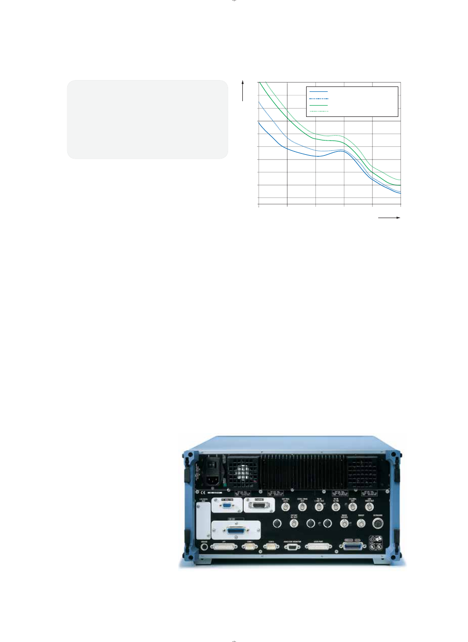
Typical SSB phase noise
100 Hz
1 kHz
10 kHz
100 kHz
10 MHz
1 MHz
Carrier offset
–70
–80
–90
–100
–110
–120
–130
–140
–150
–155
–60
¸ESIB7/26/40 at 500 MHz
¸ESIB7/26/40 at 3.5 GHz
¸ESIB26/40 at 26.5 GHz
¸ESIB40 at 40 GHz
SSB phase noise in dBc (1 Hz)
Documentation of results
Practically any type of printer can be
used for the documentation of results.
The ¸ESIB runs under Windows NT,
so all printers for which Windows drivers
are available can be employed.
Results can not only be output to a
printer but also stored on a fl oppy disk
or the internal hard disk in common
Windows formats such as EMF, WMF
or BMP. The data can be integrated into
word processing programs for the gener-
ation of test reports.
High accuracy
In the frequency range up to 1 GHz, the
¸ESIB performs level measurements
with an accuracy of ±1 dB. This is clear-
ly better than the value of ±2 dB speci-
fi ed by CISPR 16-1-1, and is achieved by
individual correction factors stored on all
modules affecting measurement uncer-
tainty. The operator can run calibration
routines for the frequency response,
display linearity and signal path gain
correction for the various instrument set-
tings, thus ensuring low measurement
uncertainty under all specifi ed environ-
mental conditions.
The required calibration sources are con-
nected internally so that autocorrection
is possible even in system applications
without any external equipment such as
cables being required. Pulse weighting
with the prescibed detectors is imple-
mented in the ¸ESIB fully digitally
by means of gate arrays and signal pro-
cessors. This makes for the best possible
reproducibility of results and does away
with the discharge times between mea-
surement periods occurring with analog
detectors. As a result, measurement
times are reduced considerably.
Selftest
The built-in selftest supports fault local-
ization down to module level. With in-
dividual correction tables being stored
on each module, defective modules can
be replaced largely without any adjust-
ment or additional instruments. Down-
times and repair costs are reduced to a
minimum.
Fig. 8:
Complete representation of spectrum: level display with PK and
AV detectors and QP and AV limit lines
Fig. 9:
Split screen with parallel detectors and bargraph
Fig. 10:
Split screen with trace and zoomed display of trace section
Fig. 11:
Frequency response of the ¸ESIB from 30 MHz up to 7 GHz
System integration
The fast data processing of the
¸ESIB makes it an ideal choice for
use in automatic measurement systems.
The IEC/IEEE bus command set
(IEC 625-2) conforms to SCPI (1994.0).
Fit for the future
The ¸ESIB family can be upgraded
by a wide variety of options to extend
its range of applications and add extra
functionality without requiring additional
instruments. The Tracking Generator
¸FSE-B10 from 9 kHz to 7 GHz
makes it easy to measure shielding
effectiveness or fi lter transfer functions.
ESIB_dat_en.indd 7
04.01.2006 13:27:22