Atec Rohde-Schwarz-ESIB Series User Manual
Page 4
4
EMI Test Receivers ¸ESIB
Up to 2 MHz, the ¸ESIB family
uses fi xed-tuned fi lters; from 2 MHz to
1000 MHz, the preselection fi lters oper-
ate as tracking fi lters.
An autorange function is available for
the automatic setting of attenuation and
gain in the RF and IF signal paths. This
function ensures the correct combina-
tion of attenuation and gain depending
on the test level or any overload of a sig-
nal stage caused by pulses or sinusoi-
dal signals. So the operator is not bur-
dened with the internal workings of the
test receiver.
To measure extremely small voltage
levels occurring, for example, in EMI
measurements on vehicle antennas in
line with CISPR 25, the ¸ESIB family
offers a 20 dB preamplifi er from 9 kHz to
7 GHz (above 7 GHz as option
¸ESIB-B2). The preamplifi er is locat-
ed between the RF preselection and the
input mixer to be protected against over-
load. With this preamplifi er, the inher-
ent noise of the ¸ESIB is lowered to
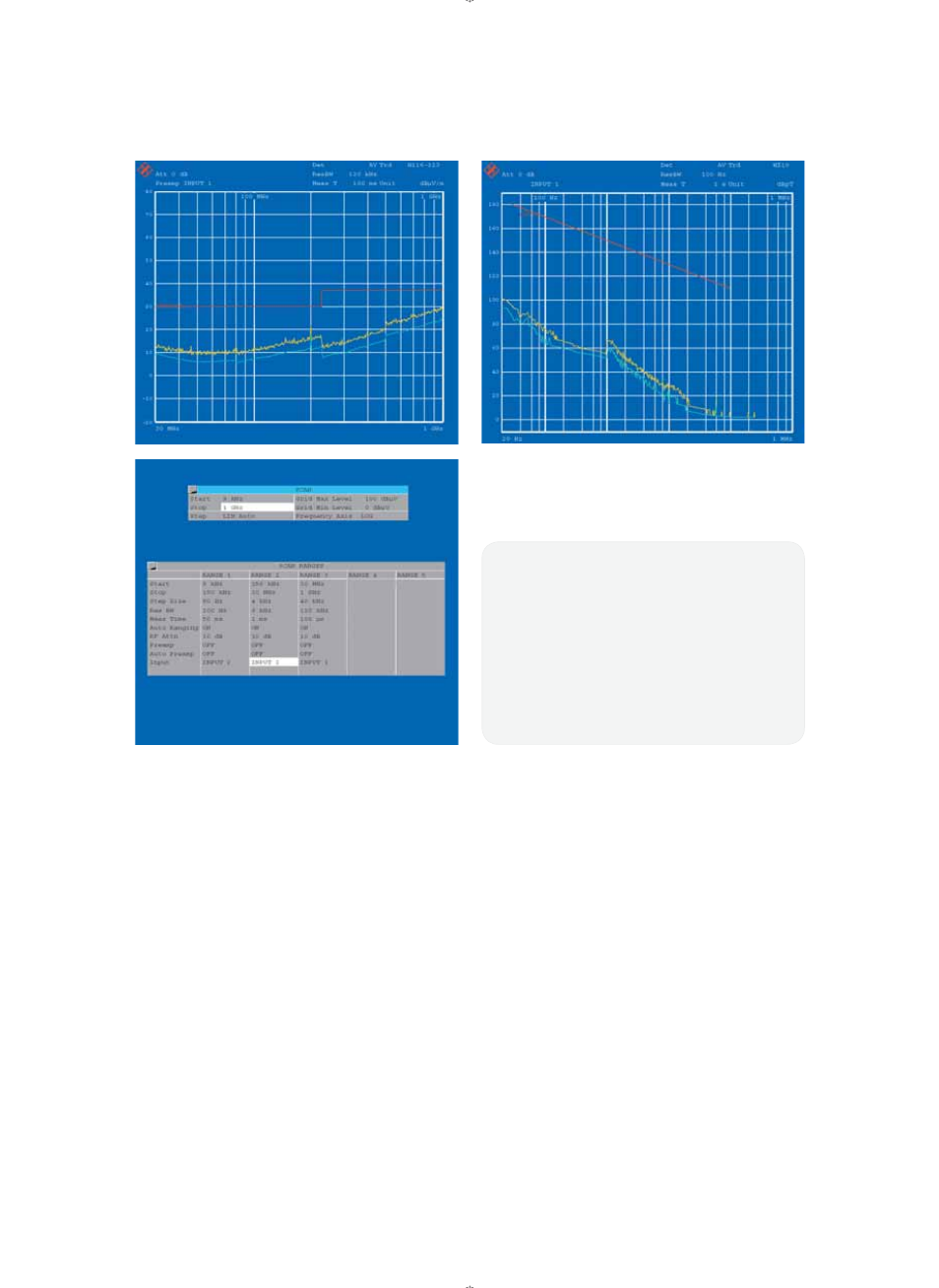
such an extent that the RFI fi eld strength
obtained in an overview measurement
using the peak detector, a log- periodic
antenna (e.g. ¸HL 223) and a 10 m
connecting cable clearly remains below
the EN 55022 quasi-peak limit (Fig. 1).
Fig. 2 shows the SCAN table stipulated
for commercial EMI measurements as a
function of the prescribed CISPR band-
widths.
To achieve high sensitivity in measure-
ments in line with MIL-STD-461D RE 101
in the frequency range from 30 Hz, the
unavoidable feedthrough of the 1st LO
at the input mixer is suppressed by self-
Fig. 1:
Sensitivity in 30 MHz to 1000 MHz range at 120 kHz IF bandwidth,
with peak detector and transducer factors for antenna + cable, dis-
played with limit lines for quasi-peak
Fig. 2:
Scan table for CISPR bands A to C/D
Fig. 3:
Inherent noise from 30 Hz to 100 kHz with limit values in line with
MIL-STD-461D RE 101, using the Shielded and Calibrated Magnetic
Field Pickup Coil ¸HZ-10
Figs. 4 to 7:
Example of transducer set: combination of antenna + cable
1
3
2
ESIB_dat_en.indd 4
04.01.2006 13:27:20