Trigger functions, Audio demodulation, Inputs and outputs (front panel) – Atec Rohde-Schwarz-ESCI Series User Manual
Page 8
Version 03.00, June 2009
8
Rohde & Schwarz
R&S
®
ESCI/ESCI7 EMI Test Receiver
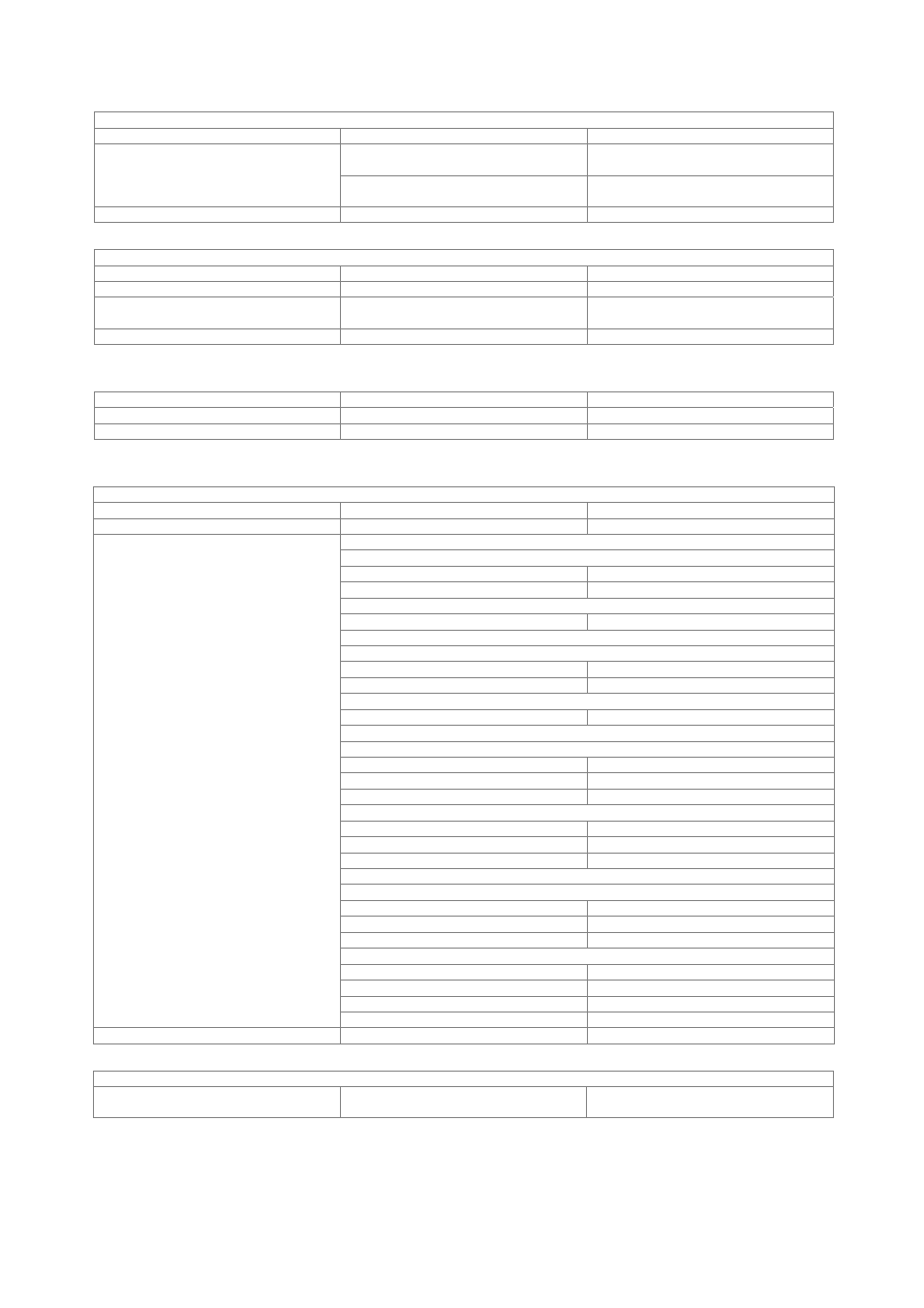
Trigger functions
Trigger
Trigger source
free run, video, external, IF level
span ≥ 10 Hz
125 ns to 100 s, resolution min. 125 ns
(or 1 % of offset)
Trigger offset
span = 0 Hz
±(125 ns to 100 s), resolution min. 125 ns,
dependent on sweep time
Max. deviation of trigger offset
±(125 ns + (0.1 % × trigger offset))
Gated sweep
Gate source
video, external, IF level
Gate delay
1 μs to 100 s
Gate length
125 ns to 100 s, resolution min. 125 ns
(or 1 % of gate length)
Max. deviation of gate length
±
(125 ns + (0.1 % × gate length))
Audio demodulation
AF demodulation modes
AM and FM
Audio output
loudspeaker and earphone jack
Marker hold time in analyzer mode
selectable
100 ms to 60 s
Inputs and outputs (front panel)
RF input
Impedance
50
Ω
Connector
N
female
RF attenuation < 10 dB, DC-coupled
R&S
®
ESCI, R&S
®
ESCI7
9 kHz to 1 GHz
< 2.0, typ. 1.5
1 GHz to 3 GHz
< 3.0, typ. 2.5
R&S
®
ESCI7
3 GHz to 7 GHz
< 3.0, typ. 2.5
RF attenuation ≥ 10 dB, DC-coupled
R&S
®
ESCI, R&S
®
ESCI7
9 kHz to 1 GHz
< 1.2
1 GHz to 3 GHz
< 1.5
R&S
®
ESCI7
3 GHz to 7 GHz
< 2.0
RF attenuation < 10 dB, AC-coupled
R&S
®
ESCI
9 kHz to 100 kHz
2.5
100 kHz to 1 GHz
2.0
1 GHz to 3 GHz
3.0
R&S
®
ESCI7
1 MHz to 5 MHz
2.5
5 MHz to 1 GHz
2.0
1 GHz to 7 GHz
3.0
RF attenuation ≥ 10 dB, AC-coupled
R&S
®
ESCI
9 kHz to 100 kHz
typ. 2.5
100 kHz to 1 GHz
< 1.2
1 GHz to 3 GHz
< 1.5
R&S
®
ESCI7
1 MHz to 5 MHz
typ. 2.5
5 MHz to 1 GHz
< 1.2
1 GHz to 3 GHz
< 1.5
VSWR
3 GHz to 7 GHz
< 2.0
Setting range of attenuator
0 dB to 70 dB in steps of 5 dB
Probe power supply
Supply voltages
+15 V DC, –12.6 V DC and ground,
max. 150 mA, nominal