Tos5101, Hipot tester, External dimensional diagrams – Atec Kikusui-TOS9201 User Manual
Page 11
21
Kikusui Electronics Corporation
TOS5101
Hipot Tester
Output block
Applied Voltage
0 to 5/ 0 to 10 kV AC and DC
AC
Maximum Rated*1
500VA / 10 kV, 50 mA
Waveform
Commercial line waveform
Voltage Regulation
Max. 15% (for max. rated load to no load)
Switching
Use of a zero turn-on switch
DC
Applied Voltage
50W / 10 kV, 5 mA
Ripple
100 Vp-p typ. at 10 kV, no load
200 Vp-p typ. at max. rated output
Maximum Rated*1
Max. 3% (for max. rated load to no load)
Output Voltmeters
Analog
Scale
10 kV full scale , AC/DC
Class
JIS Class 2.5
Accuracy
±5% of full scale
AC Indication
Mean value response / rms value scale
Digital
Full Scale
5 kV/ 10 kV full scale
Accuracy
±1.5% of full scale
AC Response
Mean value response / rms value display
Ammeter
Digital
Accuracy
±(5% + 20
μA) of upper cutoff current
AC Response
Mean value response / rms value display
Pass/fail Judgement Function
Type of Judgement
Window comparator type
●FAIL judgement
*When current detected above upper cutoff current
*When current detected below lower cutoff current
(FAIL signal generated when FAIL judgement made)
● PASS judgement
*When set time has elapsed and no abnormality is
detected
Upper cutoff current setting range
AC: 0.1 to 55 mA DC: 0.1 to 5.5 mA
Lower cutoff current setting range
AC: 0.1 to 55 mA DC: 0.1 to 5.5 mA
Judgement Accuracy
±(5% of upper cutoff current + 20
μA)
Current Detection
Integration of current absolute value fol-
lowed by comparison with reference value.
Calibration
With rms value of sine wave using a pure
resistance load.
No-load output voltage required for detection
Approx. 970 V when set to 50 mA AC
Approx. 160 V when set to 5 mA DC
Test Time Setting Range
0.5 to 999 sec (±10 ms) (timer-off function
provided)
Accuracy
±20 ms
Line Voltage
100V±10%, 50/60 Hz (Nominal voltages of
110V, 120V, 220V, 230V and 240V avail-
able as factory options.)
Power Requirements
for line voltage of 100 V
Max. 50 VA under no-load conditions
/ Approx. 600 VA at rated load
for line voltage of 100 V to 200 V
Max. 50 VA under no-load conditions
/ Approx. 600 VA at rated load
for line voltage of 220 V to 240 V
Max. 50 VA under no-load conditions
/ Approx. 610 VA at rated load
Electromagnetic compatibility (EMC)
Conforms to the requirements of the
following directive and standard.*2
EMC Directive 89/336/EEC
EN61326
EN61000-3-2
EN61000-3-3
Under following conditions
1. Used HV test leadwires which is
supplied.
2. No discharge in testing.
3. Used the shielded cable which length is
less than three meters when the
SIGNAL I/O is used.
Safty
Conforms to the requirements of the follow-
ing directive and standard. *2,4
Low Voltage Directive 73/23/EEC
EN61010-1
Class I
Pollution degree 2
Insulation resistance
30 M
Ω or more (500 V DC)
Hipot
1390 VAC, 2 seconds [between the AC LINE and chassis]
1200 VAC, 1 second [UL-approved products only]
Environment
Specifi cation range : 5
°C to 35°C / 20 %rh to 80 %rh
Operable range : 0 °C to 40°C / 20 %rh to 80 %rh
Storage range : -20 °C to 70 °C / 80 %rh or less
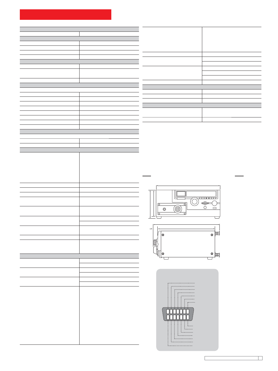
Dimensions (MAX)
430W
✕ 177(195)H ✕ 370(450)Dmm
Weight
for line voltage of 100 V
Approx. 21 kg
for line voltage of 100 V to 120 V
Approx. 23 kg
for line voltage of 220 V to 240 V
Approx. 24 kg
Accessories
High-voltage test lead
TL01-TOS (max.allowablevoltage: 5 kV /1.5m)
TL03-TOS (max.allowablevoltage: 10 kV /1.5m)
Others
14-pin amphenol plug (assembled)
*1: Continuous output time may be limited depending on current high limit reference
value and ambient temperature.
*2: Only on models that have CE marking on the panel. Not applicable to custom order
models.
*3: Not applicable to custom order models.
*4: This instrument is a Class I equipment. Be sure to ground the protective conductor
terminal of the instrument. The safety of the instrument is not guaranteed unless the
instrument is grounded properly.
430
177
MAX195
370
MAX450
45
External dimensional diagrams
7 6 5 4 3 2 1
8
9
10
11
12
13
14
READY
L FAIL
U FAIL
PASS
TEST
H.V ON
N.C
PROTECTION
INTERLOCK
RR START
RR STOP
RR ENABLE
ISOL COM
ISOL COM
[Pin Confi guration for the
SIGNAL I/O Connector]
Unit: mm