Atec Agilent-E5052A User Manual
Page 14
E5053A Microwave Downconverter
Specification Summary
Downconverter Test Port
Table 2-3. Input/output
Description
Specification
Test port input
Frequency range
3 to 26.5 GHz
Maximum Input level
+10 dBm (3 to 10 GHz band)
+5 dBm (9 to 26.5 GHz band)
Damage level
+23 dBm (nominal)
LO output
Output frequency
3 to 10 GHz
LO resolution
50 MHz
Output power
10 to 16 dBm (3 to 6 GHz)
10 to 15 dBm (6 to 10 GHz)
LO spurious
-55 dBc (Foffset > 300 Hz, typical)
IF Input
Frequency range
250 to 1250 MHz
Maximum input level
0 dBm (typical)
IF gain
0 to 35 dB (5 dB step)
Noise floor
-163 dBm/Hz
Mixer bias current
-10 to 10 mA
General Information
Table 2-4. Real Panel Information
Description
Supplemental Information
External reference signal input connector
Type
BNC, female
Input frequency
10 MHz +/- 10 Hz (typical)
Input level
-5 dBm +/- 5 dB (typical)
Internal reference signal output connector
Type
BNC, female
Input frequency
10 MHz +/- 50 Hz (typical)
Input level
2.5 dBm +/- 3 dB (typical)
USB port
Universal serial bus jack,
type B configuration, female;
provides connection to the
E5052A SSA
Line power
1
Frequency
47 to 63 Hz
Voltage
90 to 132 VAC, or 198 to 264 VAC
(automatically switched)
VA maximum
120 VA max
Table 5. Analyzer environment and dimensions
Description
Supplemental Information
Operating environment
Temperature
+10 degC to +40 degC
Humidity
20 to 80% at wet bulb temperature
< +28 degC (non-condensing)
Non-operating storage environment
Temperature
-10 degC to +60 degC
Humidity
20 to 90% at wet bulb temperature
< +40 degC (non-condensing)
Dimensions
See figures
Weight
11 kg
1. A third-wire ground is required.
E5053A Microwave Downconverter Specification Summary
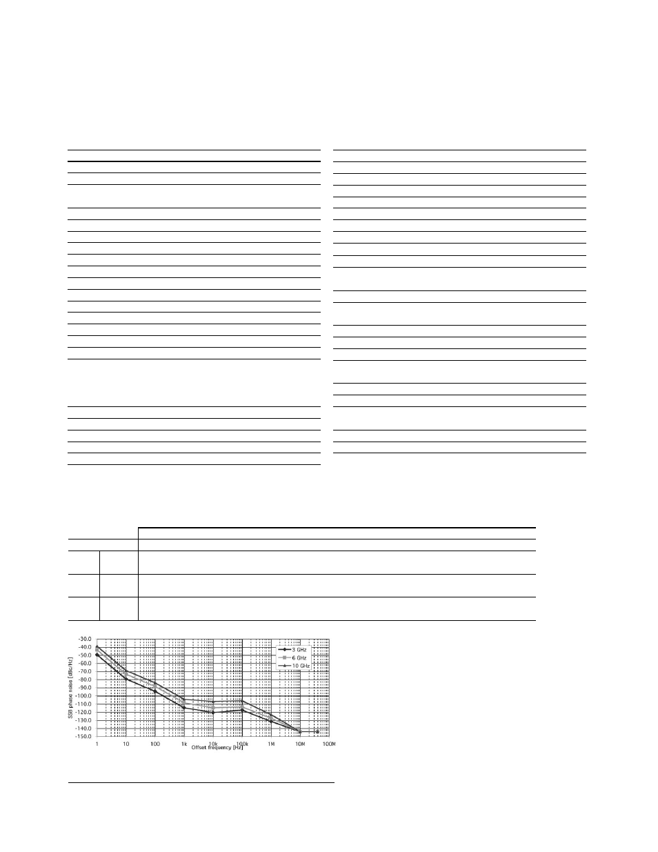
Table 2-5. E5053A downconverter LO phase noise
Offset from carrier (Hz)
Input frequency
1
10
100
1 k
10 k
100 k
1 M
10 M
40 M
3
GHz
Spec.
-110.5 -116.5 -113.5 -127.5 -140.0 -140.0
Typ.
-49.5 -79.5 -94.5 -114.5 -120.5 -117.5 -131.5 -144.0 -144.0
6
GHz
Spec.
-104.4 -110.4 -109.4 -123.4 -140.0 -140.0
Typ.
-43.4 -73.4 -88.4 -108.4 -114.4 -113.4 -127.4 -144.0 -144.0
10
GHz
Spec.
-100.0 -103.0 -102.0 -119.0 -140.0 -140.0
Typ.
-39.0 -69.0 -84.0 -104.0 -107.0 -106.0 -123.0 -144.0 -144.0
Figure 2-3. E5052A downconverter LO phase noise (typical)
14