Atec Aeroflex-IFR-3416 User Manual
Page 4
T he 2U rack height ensures the 3410 series occupies minimal space
in a manufacturing rack or on the engineer's bench, allowing the pro-
vision of more compact test systems. T he full rack width ensures
easy stacking of instruments while the light weight allows for easy
carr ying in the laborator y or the field.
Range
250 kHz - 2 GHz (3412)
250 kHz - 3 GHz (3413)
250 kHz - 4 GHz (3414)
250 kHz - 6 GHz (3416)
Resolution
1 Hz, accuracy as frequency standard
The carrier output phase can be advanced or retarded in increments of
0.036°.
FREQUENCY SETTING TIME (NON-LIST MODE)
After receipt of the GPIB interface deliminator (terminator), 23°C ± 5°C
Phase Noise Mode Optimized > 10 kHz
< 5.5 ms, typically 4 ms, 375 MHz, to be within 200 Hz
> 375 MHz, to be within 0.1 ppm
Phase Noise Mode Optimized < 10 kHz
< 3 ms, typically 2.5 ms, 375 MHz, to be within 200 Hz
< 2.5 ms, typically 2 ms, > 375 MHz, to be within 0.1 ppm
FREQUENCY SETTING TIME (OPTION 010 LIST MODE)
After external trigger in List Mode, 23°C ± 5°C
Phase Noise Mode Optimized > 10 kHz
< 4 ms, typically 3 ms, 375 MHz, to be within 200 Hz
> 375 MHz, to be within 0.1 ppm
Phase Noise Mode Optimized < 10 kHz
<600 s, typically 500 s, 375 MHz, to be within < 200 Hz
<500 s, typically 450 s, > 375 MHz, to be within 0.1 ppm
The RF output is controlled by an ALC system in normal operation.
When IQ modulation is enabled alternative control modes are available
to optimize the performance of the signal generator.
Range
Electronic Attenuator
10 MHz
-140 to + 13 dBm
2 GHz
-140 to + 16 dBm
3 GHz
-140 to + 16 dBm
3.75 GHz
-140 to + 13 dBm
4 GHz
-140 to + 10 dBm
6 GHz
-140 to + 8 dBm
Mechanical Attenuator
10 MHz
-140 to + 16 dBm
2 GHz
-140 to + 19 dBm
3 GHz
-140 to + 16 dBm
No Attenuator
10 MHz
0 to + 21 dBm
3 GHz
0 to + 22 dBm
3.75 GHz
0 to + 20 dBm
4 GHz
0 to + 17 dBm
6 GHz
0 to + 18 dBm
When AM is selected the maximum RF output is linearly reduced by up
to 6 dB depending on the requested AM depth.
When IQ modulation is selected maximum output is reduced by 6 dB
below 100 MHz.
Resolution
0.01 dB
RF Level Units
Units can be set to µV, mV, V EMF or PD; dB relative 1 µV, 1 mV, 1 V
EMF or PD; or dBm. Conversion between dB and linear units may be
achieved by pressing the appropriate units key (dB or V, mV or µV).
RF Output Accuracy (@ 23°C ± 5°C)
Electronic Attenuator
RF Mode
-127 to -30 dBm
> -30 dBm
Auto
2 GHz
± 0.75 dB
± 0.50 dB
3 GHz
± 1.00 dB
± 0.75 dB
-110 to -30 dBm
> -30 dBm
6 GHz
± 1.25 dB
± 1.00 dB
Mechanical Attenuator
RF Mode
-127 to -28 dBm
> -28 dBm
Auto
2 GHz
± 0.75 dB
± 0.50 dB
3 GHz
± 1.00 dB
± 0.75 dB
No Attenuator
RF Mode
> 0 dBm
Auto
2 GHz
± 0.50 dB
3 GHz
± 0.75 dB
6 GHz
± 1.00 dB
Level Accuracy With IQ Modulation
For constant envelope modulation systems: typical standard level error
± 0.15 dB
For non-constant envelope modulation systems: typical standard level
error ± 0.25 dB
Temperature Stability
± 0.01 dB/°C, 3 GHz
± 0.02 dB/°C, 4 GHz, ± 0.02 dB/°C typical, 6 GHz
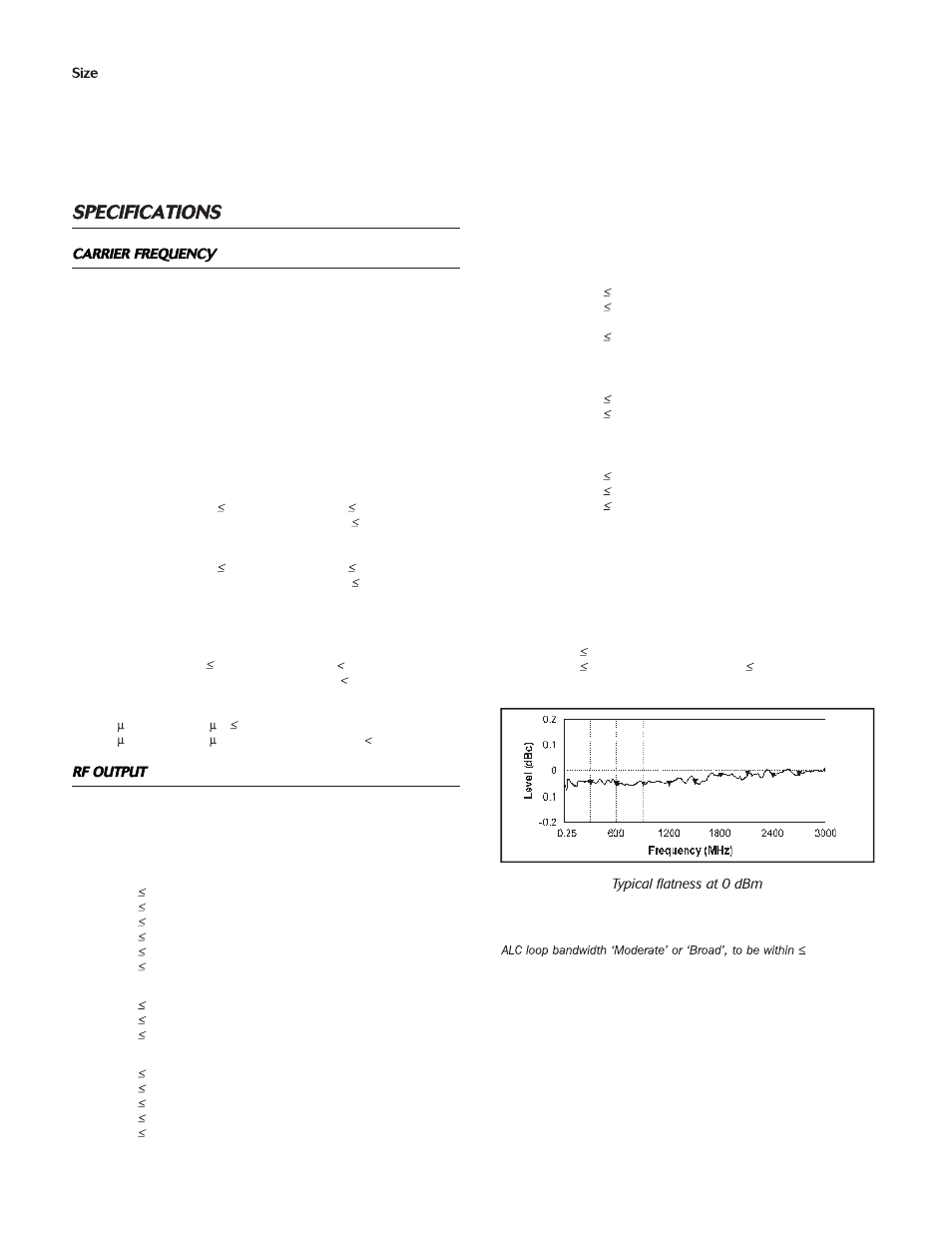
RF Flatness
LEVEL SETTING TIME
Electronic attenuator, Option 003 is assumed in all cases.
0.3 dB
Level Setting Time (Non-List Mode)
After receipt of the GPIB interface deliminator (terminator), 23°C ± 5°C
< 4.5 ms, typically 2.5 ms
Level Setting Time (Option 010 List Mode)
After external trigger in List Mode, 23°C ± 5°C
< 3 ms, typically 1.5 ms