Battery installation, Preparation/mounting, 16 battery installation – Alpha Technologies Te45 User Manual
Page 38
Alpha Technologies Ltd.
057-106-C0 Rev D
Burnaby, British Columbia. Telephone: 604 436 5900 Fax: 604 436 1233.
Page 29 of 38
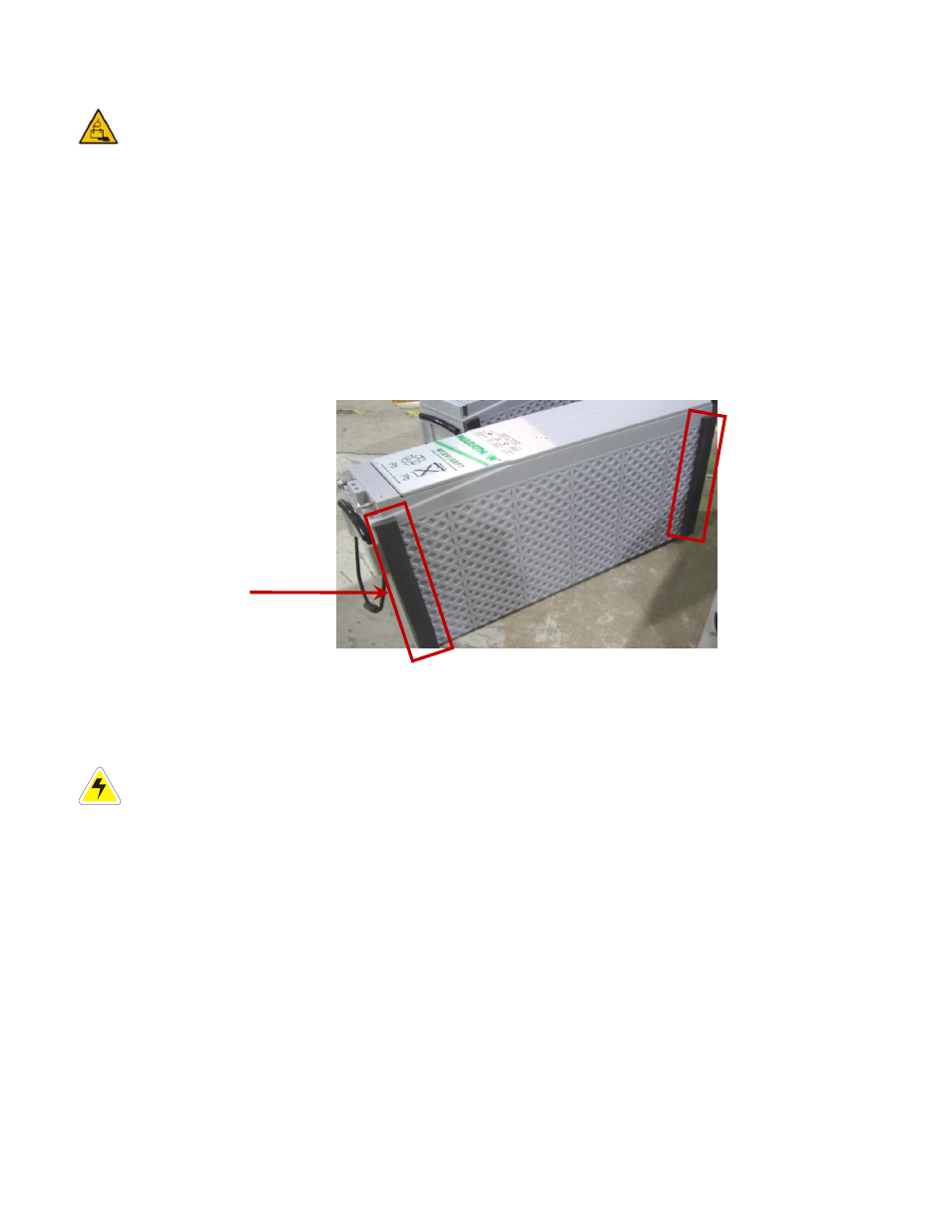
Install gaskets at
the front and rear
of each of 3 of 4
batteries.
4.16 Battery installation
WARNING: Follow the battery manufacturer’s safety recommendations when working around
battery systems and review the safety instructions provided in this manual.
4.16.1 Preparation/mounting
Make sure the enclosure is properly mounted and secured before starting the battery installation.
The batteries should be located in a temperature-controlled environment (Tempest). Regulate the temperature
to approximately 25°C (77°F). Significantly lower temperatures reduce the battery performance and higher
temperatures decrease the battery life.
Clean the batteries cells according to the battery manufacturer's recommendations. First neutralize any acid
with a baking soda and water solution, rinse the batteries with clean water, and then wipe them dry.
Install gaskets at the front and rear of each 3 of 4 batteries.
4.16.2 Battery installation in Alpha Tempest power systems
Verify that all battery breakers, DC circuit breakers, and fuses on the distribution panels are either
in the OFF position or removed. For each of the following steps, verify that the rubber terminal caps
or plastic covers are installed and completely cover the positive and negative terminal connections.
1. Apply a corrosion-inhibiting agent, such as NO-OX-
ID “A”™, on all battery terminal connections.
2. Lift each battery onto the front edge of the shelf, and then slide the battery into the shelf.
3. Ensure that each battery output cable reaches the [+] and [
–] terminals of the series battery string. Make sure
that the batteries are oriented for easy installation of the inter-
unit “series” connectors.
4. Remove any NO-OX-
ID “A”™ grease from the battery terminals.
5. Burnish the terminal posts with a non-
metallic brush, polishing pad, or 3M Scotch Brite™ scouring pad.
6. Apply a light coating of NO-OX-
ID “A”™ grease to the terminal posts.
7. If lead plated inter-unit connectors are used, they should also be burnished and NO-OX-
ID “A”™ grease
applied as above.
8. Install the battery shelf retaining brackets.
9. Install the inter-unit connectors.
Figure 29
– Gasket installation on batteries