2 front panel – Alpha Technologies Micro, Micro XL, Micro XL3 UPS User Manual
Page 11
9
017-237-B0 Rev A
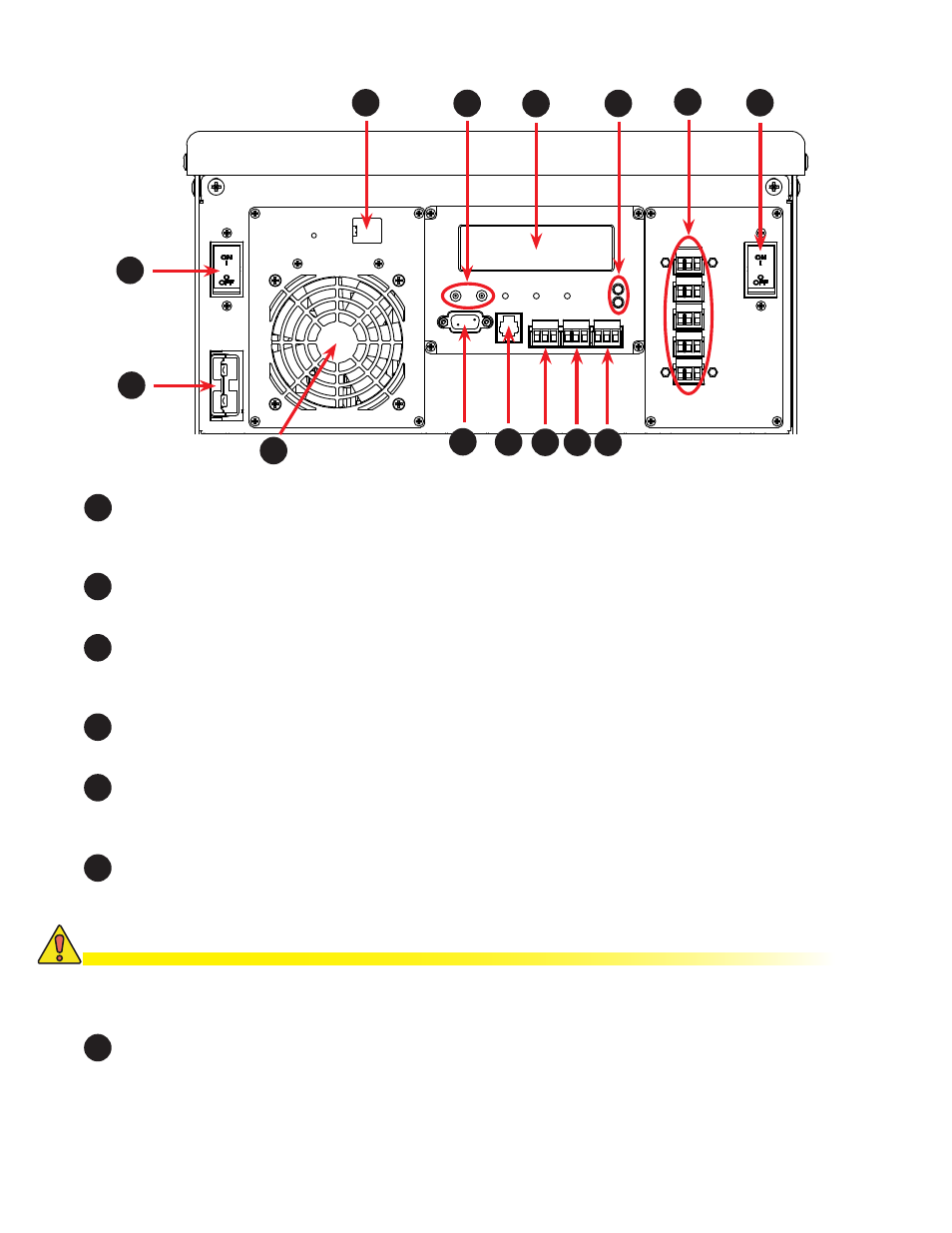
2.2 Front Panel.
Figure 3 — Front panel description
Battery Circuit Breaker
This circuit breaker provides over-current protection and is uses as an on/off switch for the battery power. It must
be switched on for proper UPS operation.
2
Battery Connector
The battery connector connects the external batteries to the Alpha Micro.
3
Internal Fan
This microprocessor-controlled fan regulates the Alpha Micro’s internal temperature for optimum performance. It
must not be blocked. If the fan fails, an alarm is generated.
4
Ethernet
This optional, RJ-45 connector is the Alpha Micro Ethernet connector.
5
AC Input Circuit Breaker
This circuit breaker is an on/off switch for line power into the Alpha Micro and provides input protection. It must
be ON for proper UPS operation.
6
Battery Voltage Test Points
These let you measure the battery voltage. They accept 2 mm diameter test probe tips. The battery circuit
breaker must be on to measure the voltage.
1
13
1
2
5
11
3
4
7
10
8
12
9
11
6
CAUTION!
Do not use the battery voltage test points as a power outlet. Failure to do so may dam-
age the internal electronics.
7
RS-232 Port
This DE-9 connector allows a straight-through DE-9 to DE-9 connector cable to be used to connect the
Alpha Micro to a computer for remote control and monitoring.