Float installation details – Franklin Fueling Systems TSP-IGF2 Two Inch Floats User Manual
Page 2
Float Installation Details
Verify that the color of the water float agrees with the
•
product to be used within the storage tank (Figure 1).
Use a small flat bladed screwdriver to pry‑off/remove the
•
E‑Ring from the bottom of the probe shaft, then remove
the stainless steel float retainer washer. See Figure 2.
Install the floats per Figure 2. Product float first (magnet
•
end up) and then the water float (magnet end up).
Install the stainless steel, “float retainer” washer at the
•
bottom of the probe shaft. Slide the E‑Ring into the
grove below the stainless steel washer. See Figure 2.
Install a 2 or 3 inch isolation bushing (
•
if required by
local/State codes for steel tanks), 2 or 3 inch tank riser
(length = As Required), 2 or 3 inch to 4 inch bell reducer
fitting, 4 inch riser (length = As Required), and the
TSP‑K4A riser cap adapter. See your installation guide
(part number 000‑1050).
Install, wire, and test the TSP‑LL2 liquid level probe. See
•
your installation guide (part number 000‑1050).
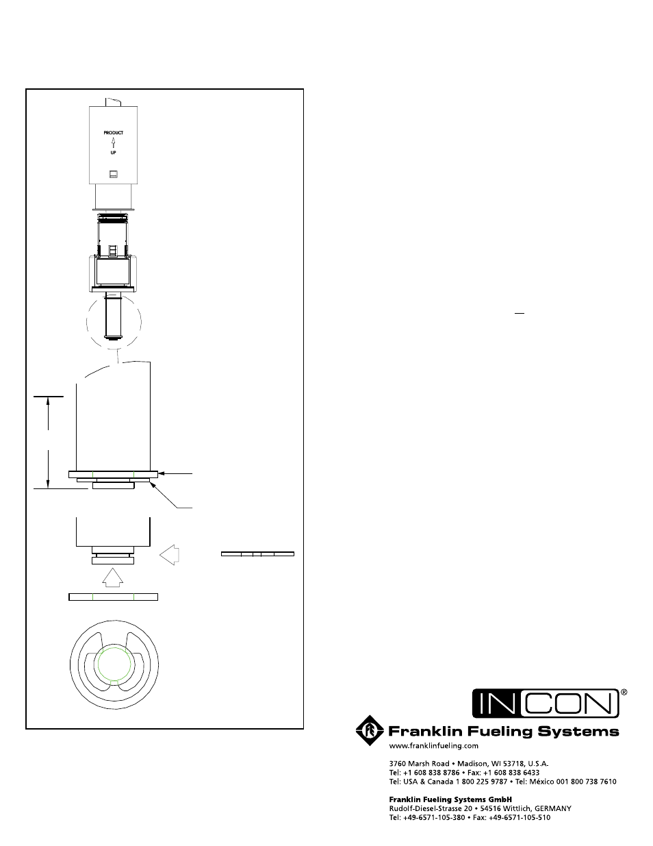
Figure 2:Float & Retainer Installation Detail
E-ring
E-ring
2.00
Bottom View of
Probe Shaft
Showing Stainless
Steel Washer and
E-ring Retainer
Stainless Steel Washer
Stainless
Steel Washer
End of
Probe Shaft
Probe Shaft
Float
Retainer
Detail
Product
Float
(Magnet
End Up)
Water /Interface Float
(Magnet End Up)
©2007 FFS 000‑1176 rev. C