Overview, Testing the tsp-his, Materials required – Franklin Fueling Systems TSP-HIS User Manual
Page 2: Installation sequence
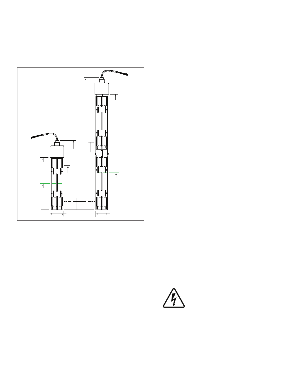
Overview
The TSP-HIS sensor is an intelligent BriteSensor ® that
is used to monitor the brine levels inside hydrostatic
interstitial reservoirs of double walled tanks. A low brine or
high brine level are alarm conditions and indicate a leak in
either the outer tank or the inner storage tank. The TSP-
HIS-XL sensor is an extra long version of this sensor
(see Figure 1).
21.7 INCH
(551.2 mm)
2.5 Inch (63.5 Mm)
Max. Dia. [ Typ ]
TSP-HIS
Hydrostatic
Interstitial Sensor
(BriteSensor
®
)
4 to 4.5 INCH
(102 TO 114 mm)
Normal Brine Level
Datum
8.6 INCH
(225 mm)
Ref.
7.5
Inch
(190.5
mm)
High
Brine
Level
1.0 INCH
(25.4 mm)
Low
Brine
Level
11.8 inch
(299 mm)
2.38 Inch (60.5 Mm)
DIA. [ TYP ]
6.25 TO 5.75 INCH
(159 TO 146 mm)
Normal Brine Level
11.0 Inch
(279.4
mm)
High
Brine
Level
18.76 INCH
(476.5 mm)
REF.
TSP-HIS-XL
Extra Long
Hydrostatic
Interstitial Sensor
(BriteSensor
®)
Figure 1: TSP-HIS Dimensions
Both sensors have upper and lower magnetic reed switch
floats, which detect a change in the interstitial reservoir
brine level. The sensors use intrinsically safe (I.S) leak
detection circuits and are approved for use in these Class
1, Division 1, Group D Hazardous Areas.
Like other BriteSensors, these sensors have a
microprocessor that analyze the environmental conditions
at the sensor and transmits data to the Automatic Tank
Gauge console. The TSP-HIS sensors detect and
communicate: a HIGH BRINE alarm level, a LOW BRINE
alarm level, and a NORMAL no-alarm state (lower float
submerged & upper float dry), plus it transmits a specific
sensor ID code.
Included with the sensor are: no-strip electrical wire
connectors, 25 feet of cable (attached), a Model ID tag,
and a cord-grip fitting for connection to a weatherproof
electrical junction box (see diagrams). Be sure to check
the Model ID tag before installing the sensors as they can
be confused with the similar looking TSP-DDS and TSP-
DTS sensors.
A vented riser cap (model TSP-KV4) is required
for this installation so the brine level can rise or fall
(hydrostatically) along with atmospheric pressure without
building up positive or negative pressures inside the
interstitial area.
Testing the TSP-HIS
Dip the sensor in 2 inches (50.2 mm) or water and remove
after one minute to produce a LOW BRINE alarm. Rotate
the sensor 180 degrees (float up) to cause a HIGH BRINE
alarm at the ATG console. Test the sensor for proper
operation on a yearly basis, or as required per local code.
Materials Required
Optional – TSP-DB1 epoxy seal kit for no-strip electrical
•
connectors – recommended for sites: within flood zones,
high groundwater tables, with poor drainage, or when
Junction Boxes are not used.
1/2 or 3/4 inch NPT (National Pipe Thread, tapered),
•
Rigid Metal Conduit (RMC), or non-metallic (PVC)
conduit if allowed by local code.
EYS Seal fittings and epoxy to fill the fitting after
•
operational testing is completed.
Weatherproof junction box, gasket, and cover, plus a
•
3/4 to 1/2 inch NPT reducing bushing if 1/2 inch RMC is
used – see the ATG Installation Guide for recommended
electrical junction boxes
Wire: THHN, TFFN or THWN, 18 AWG: Red, White, &
•
Black, or Alpha Cable # 58113, 0.131 O.D. – 1,500 feet
(457 meters) max. length. Alpha cable #58113 (INCON
P / N 600-0063) must be used when using nonmetallic
(PVC) conduit.
Slip joint pliers to seat the no-strip, self-sealing wire
•
connectors – connectors are supplied with the sensor
Standard adjustable or pipe wrench for a 2 inch square
•
fitting.
UL classified thread sealant or pipe dope.
•
TSP-KV4 vented riser cap (order separately)
•
Installation Sequence:
1. Install manhole.
2. Install conduit, EYS fittings, and weatherproof
junction box (Refer to Figure 2).
3. Shut off power to the ATG.
ELECTRICAL DANGER. To avoid
electrical shock hazards, ensure all
power going to the ATG console is
turned off, tagged, and locked-out
at the power panel before doing any
maintenance or installation work at the
ATG console
4. Pull the sensor cable through the cord grip fitting
at the junction box (leave enough cable to allow
for the installation of the sensor in the interstitial
area). Before pulling wires, mark them to avoid
confusion when connecting to the ATG console.
2