Overview, Materials required, Installation sequence – Franklin Fueling Systems TSP-ULS User Manual
Page 2
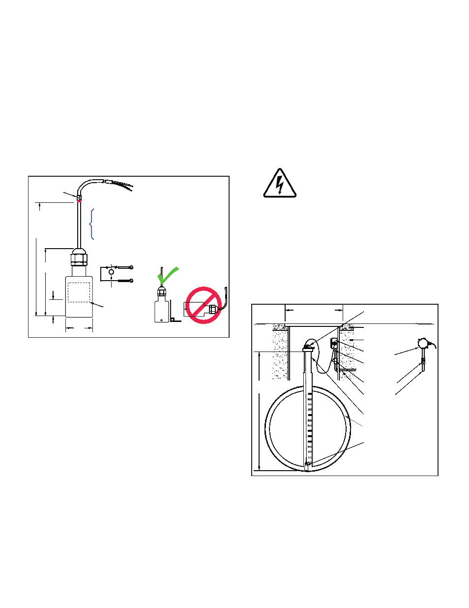
Overview
The TSP-ULS is a Standard sensor that is used to detect
the presence of a liquid in the normally dry Class 1, Division
1, Group D Hazardous Areas of: sumps, dispenser-pans,
and interstitial areas of double-wall steel storage tanks.
The sensor is supplied with electrical connectors, 25 feet of
cable, and a cord-grip fitting (see diagrams). The TSP-ULS
uses magnetic-float/reed-switch technology (the sensor
must be suspended vertically (See Figure 1) so the float
can rise freely with the level of a liquid).
When the float rises more than 1/2 of an inch, the
magnetically sensitive reed switch will open (see internal
float in Figure 1). An open circuit is recognized as an alarm-
condition at the intrinsically safe (I.S) leak detection circuits
of the FFS (Franklin Fueling Systems) ATG console.
Magnetic
Reed float switch
opens when float
moves up 0.52 inch
(13.2 mm)
(Wht)
(Blk)
(Wht)
(Blk)
Typical Sensor Input
Interface (Channel N):
For installation in double-walled steel tanks, the
install height is measured from the top of the riser
to the bottom of the interstitial space in the tank
1.48
(37.6 mm)
0.52
(13.2 mm)
3.62
(92 mm)
C NC
Install Height =
Measured height
+1.5 inch (38.1 mm)
allowance for
TSP-K12 height
Colored
marking
pen/tape
Gnd
In
Suspend Sensor Veritcally
Figure 1: TSP-ULS Dimensions
Materials Required
• Optional – TSP-DB1 Epoxy Seal kit for no-strip electrical
connectors – recommended for sites: within flood zones,
high groundwater tables, with poor drainage, or when
junction boxes are not used.
• 1/2 or 3/4 inch NPT (National Pipe Thread, tapered),
Rigid Metal Conduit (RMC) or nonmetallic (PVC) conduit
if allowed by local codes.
• EYS Seal fittings and Epoxy to fill the fitting after
operational testing is completed.
• Weatherproof junction Box, gasket, and cover, plus a
3/4 to 1/2 inch NPT reducing bushing if 1/2 inch RMC is
used – see the ATG Installation Guide for recommended
electrical Junction Boxes.
• Wire: THHN, TFFN or THWN, 18 AWG, White & Black,
or Alpha Cable # 58411, 0.114 O.D. – 1,500 feet (457
meters) max. length. Alpha cable #58411 must be use
with nonmettalic conduit.
• Slip joint pliers to seat the no-strip, self-sealing wire
connectors – connectors are supplied with the sensor.
• UL Classified Thread Sealant or pipe dope.
• *TSP-KI2 Riser Cap for 2-inch riser pipes, includes a
pre-installed 1/2 inch NPT compression gland (cord grip)
fitting. Other riser caps are available for different riser
pipe sizes – consult your factory rep.
• * Riser pipe – 2 inch diameter (OD), threaded at one end
(NPT-14) with all rough edges removed / deburred from
the inner edges.
* = Needed for installation in UST interstitial areas (Figure 2)
Installation Sequence
1. Install Riser Pipe, Manhole.
2. Install conduit, EYS fittings, and weatherproof
junction box.
3. Shut off power.
ELECTRICAL DANGER Avoid electrical
shock hazards: ensure all power
going to the ATG console is turned off,
tagged, and locked-out at the power
panel before doing any maintenance or
installation work at the ATG console.
4. Interstitial installation – see Figure 1 & 2, measure
the INSTALL HEIGHT needed and add 1.5 inches
= total height. Mark the total height on the sensor
cable as shown in Figure 1, pull the cable through
the TSP-KI2 Riser Cap and cord-grip until the mark
shows at the top of the cord grip fitting. Tighten the
fitting and lower the sensor into the interstitial area
of the tank as shown in Figure 2.
Double-wall
steel tank
Install height
(as measured)
Cover for
14 inch (35.56 cm)
Min. dia. manhole
Manhole
2 inch riser pipe
1/2 or 3/4 inch conduit
Eys seal Fitting
Interstitial area (dry)
TSP-ULS
Sensor
Concrete slab
per NFPA 30
TSP-K
I2 riser cap
(with cord grip - compression fitting)
Clean fill material
(Gravel typical)
Weatherproof
Junction box
Compression
fitting (Cord grip)
Figure 2: Installation in Double-Walled Steel Tanks
5. Pull the sensor cable through the cord grip fitting at
the junction box (also see Figure 3 for installation
within a sump) and tighten all remaining cord-grip
fittings. Trim wire / cables to a 6 or 8 inch (15 or
20 cm) service-loop, and splice the sensor and
console cable/wires together as shown in Figure 4.
2