Franklin Fueling Systems TSSP-TMPTR Thermal Printer User Manual
Page 2
2
Printer Installation
The following instructions are for the addition of an internal
printer or replacement of an existing printer in a T5 Series
Fuel Management System.
Note: The thermal printer requires controller module
firmware rev 1.5 or higher. Refer to page 7
Updating Console Firmware.
Included with Printer:
• Plastic Bezel
• Thermal Printer on PCB (Printed Circuit Board)
• Hardware includes:
• (2) stand-offs
• Mounting screws
(Quantity, size and
use shown in chart)
Note: Use only the
provided hardware
to mount the printer.
Installation Procedure
Disconnect power before opening the
console cover.
1. Open the Tank Gauge front door.
2. Remove the front door’s inside cover plate by
unscrewing the screws located on the plate.
(Number of screws vary by model).
Figure 1: Remove Inside Cover Screws
To Retrofit a Printer in a Console Without One
a. Remove the 4 nuts that secure the blank-off
plate.
b. Remove the plate (blank-off plate may stick to
the overlay).
c. Carefully cut out the part of the overlay that
covers the printer opening using a sharp knife.
Go to step 9.
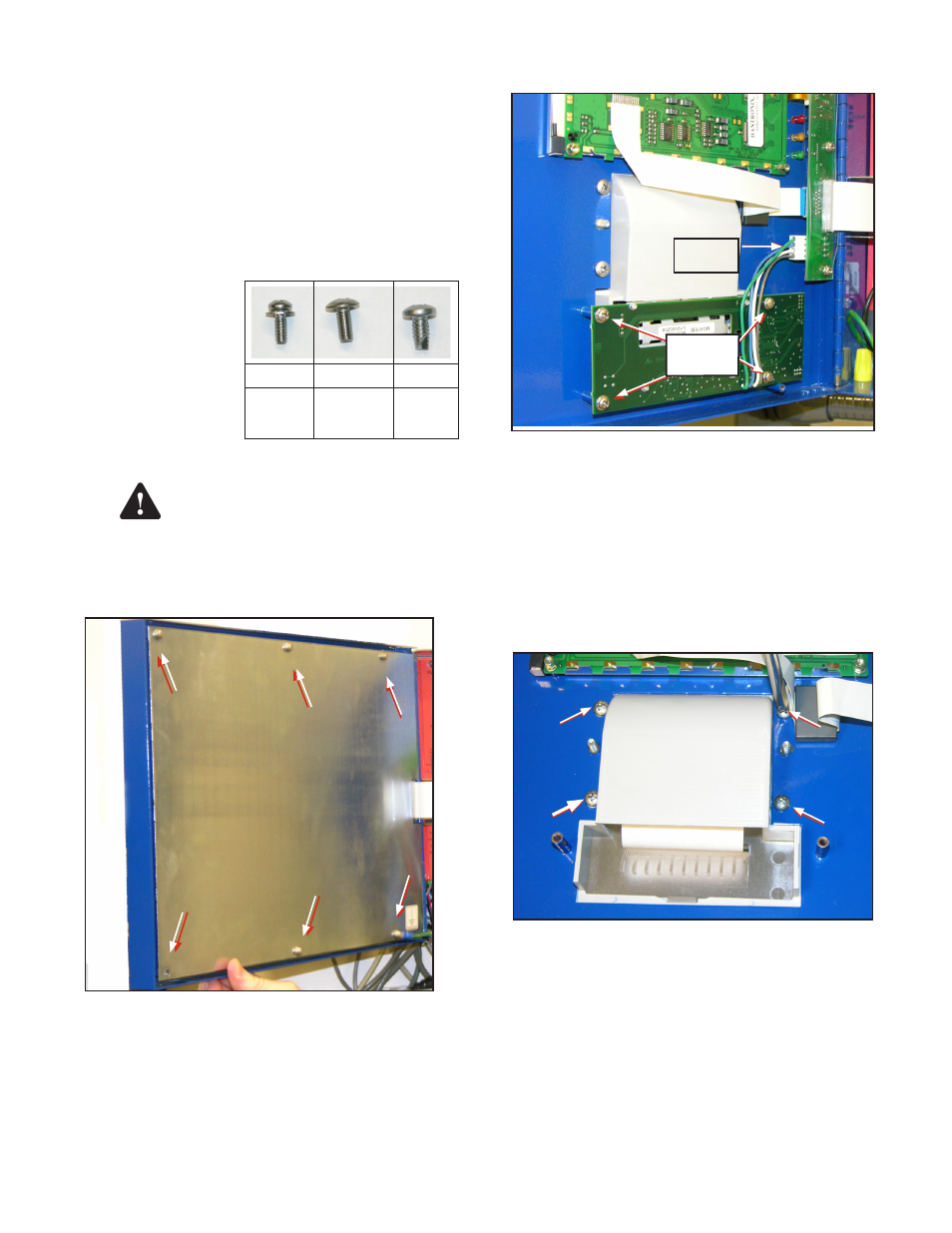
3. Disconnect the cable that connects the impact
printer to the interface board in the front door.
Remove
Cable
Remove
Screws
Figure 2: Disconnect Old Printer
4. Remove the roll of paper from the printer.
5. Remove the 4 screws that hold the impact printer
to the front door.
Note: Be careful not to damage the ribbon cable.
6. Pull the printer gently and slowly a couple of
inches away from the door. Completely remove the
impact printer board.
7. Remove the 4 screws that hold the printer’s plastic
cover printer to the front door.
Figure 3: Remove Plastic Cover
8. Remove the plastic cover.
9. Place the new plastic bezel over the cutout in the
front door. Fasten the bezel to the enclosure using
the two #10 self-tapping screws supplied Start the
screws in the lower two mounting holes. Do not
tighten screws all the way at this time. These screws
will be tightened after installing the printer assembly.
10. Install the 2 stand-offs on the studs located next to
the printer opening (Figure 4).
Warning
(4) #6
(2) #8
(2) #10
For lower
4 holes in
the PCB
For top of
PCB, in
stand-offs
For
Plastic
Bezel