Franklin Fueling Systems Console DTU (Data Transfer Unit) User Manual
Page 2
2
Step 4 – Bus Termination Jumper Removal
The Console DTU will provide system bus termination
when installed and running. Therefore the system bus
termination currently provided by the Power Supply
Module needs to be removed. Refer to the TS-5XXX
Series Installation Guide for instructions on how to remove
a module.
Be extremely careful when removing the power supply
module so it does not rub against any other part of the
system. After it is removed from the system, locate the
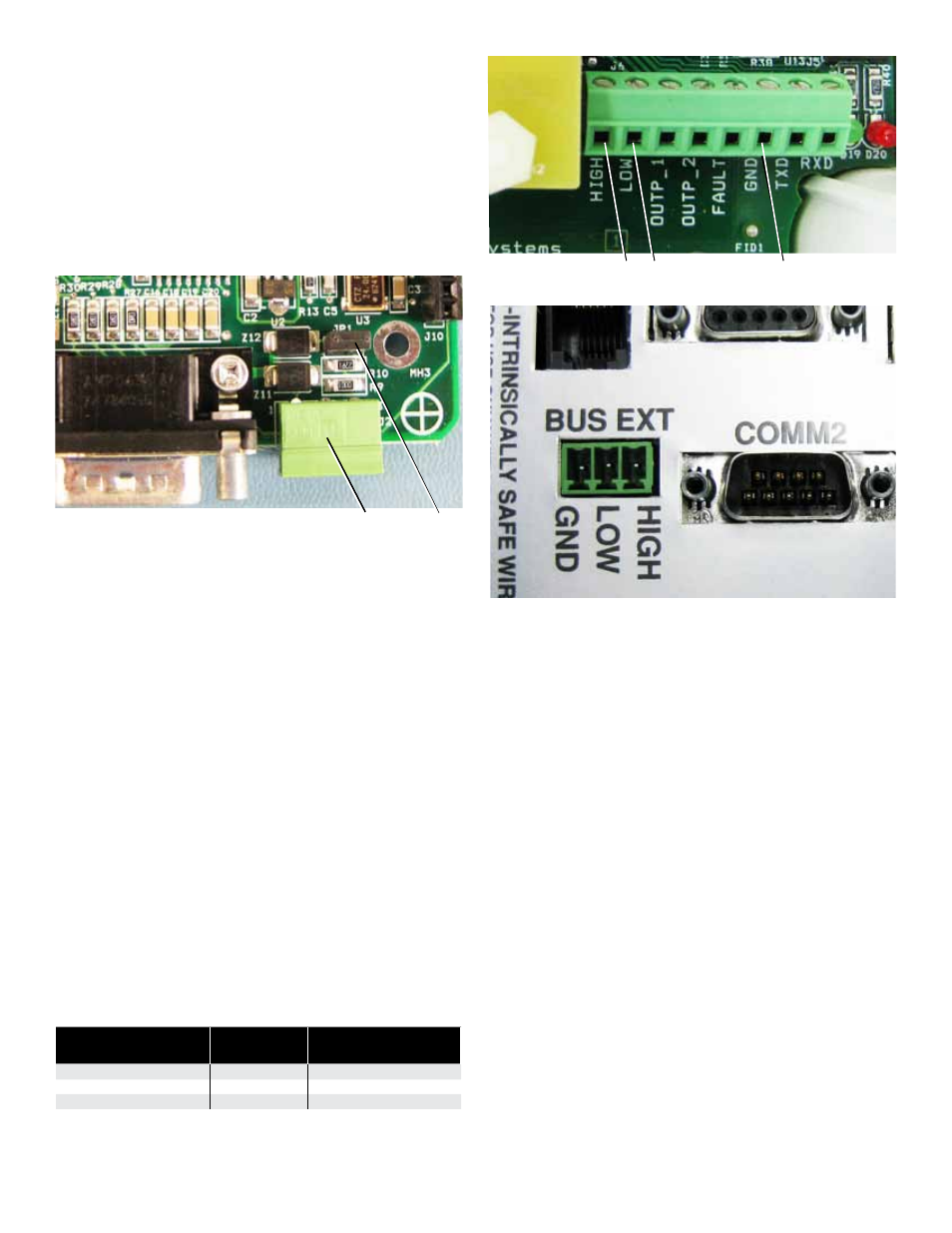
system bus termination jumper JP1 and remove it (Figure 2).
JP1
BUS EXT
Figure 2: JP1 Location on the Power Supply Module
Re-Install the power supply module, securing it properly in
place and replace the communication bracket as required.
Step 5 – Data Connection
The Console DTU acts as an external System Console
module and therefore must be connected to the system
bus. This is made possible via the external BUS EXT
connection, located on the power supply module.
The bus connection requires 2-wire shielded cable and
FFS recommends Belden 87761. On the Console DTU,
the cable enters through the Intrinsically Safe (I.S.)
opening but is connected outside of the I.S. area, which is
not used in the Console DTU. Therefore the I.S. shield will
need to be removed and discarded. Secure the bus cable
on the Console DTU side using a cord grip.
On the System Console communications bracket, locate
the BUS EXT connector (Figure 4). The connector is
removable for convenient wiring. Refer to the following
table and make the proper BUS (HIGH, LOW, GND)
connections (Figure 3). To make the necessary
connections between the System Console and the DTU,
plug the BUS EXT connector back into the System
Console. Secure the bus cable so it is not accidentally
disconnected.
Belden Cable
BUS EXT
Console DTU
Connection
Red Wire
HIGH
HIGH
Black Wire
LOW
LOW
Shield
GND
GND
High Low
Ground
Figure 3: Console DTU BUS EXT Connection
Figure 4: Console Side BUS EXT Connection
Step 6 – Review All Connections
Review power and data connections and make sure the
cable is attached securely. Finally replace the Console
DTU Cover.
Step 7 – Power Up
Return power to the System Console and the newly
installed Console DTU.
Related Documents
000-2146 DTU Dispenser Retrofit Manual
000-2142 T5 Console Programming Manual,
rev D or higher
000-2150 T5 Installation Manual
000-2058 VRM IOM manual rev C or higher