Installation, cont’d – Extron Electronics SW 2_4 ARxi User Guide User Manual
Page 9
SW Switchers • Installation
SW Switchers • Installation
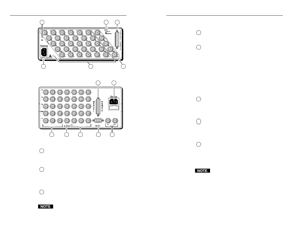
Installation, cont’d
capability. This allows the inputs to be used as
outputs. See “Features” on page 1-8.
4
Output connectors —
BNC female output connectors
See page 2-7 for information about cabling the
connectors.
5
Mode switch
(SW ARxi and SW AR HVxi only) —
Toggles between auto-switch mode and manual
mode. (The same functionality is provided on SW
AR MX, SW AR MX HV, and SW 6 Component via
front panel buttons.)
Auto —
Allows the switcher to automatically select
the highest input number that has a sync signal
on the sync input connector.
Manual —
Allows you to select the input by pressing
the front panel buttons or by using a remote
control device.
6
Contact/manual remote connector —
One 25-pin
D female connector that allows you to connect an
optional remote control device or a third-party
remote control device. See page 2-14 for more
information.
7
RS-232 connector —
One 9-pin D female connector
that allows you to attach a computer or another
device for remote control of the switcher.
See page 4-7 for more information. (SW AR MX,
SW AR MX HV, and SW 6 Component only.)
8
Looping BNCs —
Provide communications between
switchers when two or more switchers are looped
together. (SW AR MX, SW AR MX HV, and
SW 6 Component only. The same functionality is
provided on the SW ARxi and SW AR HVxi switchers
via pins 12 and 24 of the contact remote connector.)
The SW 2 AR MX and SW 6 Component switchers
do not provide looping capability.
Figure 14 — SW 6 AR HVxi
xi
xi
xi
xi rear panel
Figure 15 — SW 6 AR MX HV rear panel
1
AC power connector —
Standard AC power
connector attaches the switcher to any power source
from 100VAC to 240VAC, operating at 50 Hz or
60 Hz.
2
Power LED
(SW ARxi and SW AR HVxi only) —
Lights to indicate that power is supplied to the
switcher. (The power LED on an SW AR MX,
SW AR MX HV, and SW 6 Component switcher is
located on the front panel.)
3
Input connectors —
BNC female input connectors.
See page 2-7 for information about cabling the
connectors.
SW AR MX, SW AR MX HV, and
SW 6 Component switchers have bidirectional
2-5
2-4
1
3
4
90-240 VAC, 50/60 Hz
FUSE: 250V, 400mA SLO-BLO
INPUTS
INPUTS
5
3
1
2
4
6
1
3
3
4
6
7
8
2
5
6