Ab c, Installation, cont’d – Extron Electronics SW 2_4 ARxi User Guide User Manual
Page 13
SW Switchers • Installation
SW Switchers • Installation
Installation, cont’d
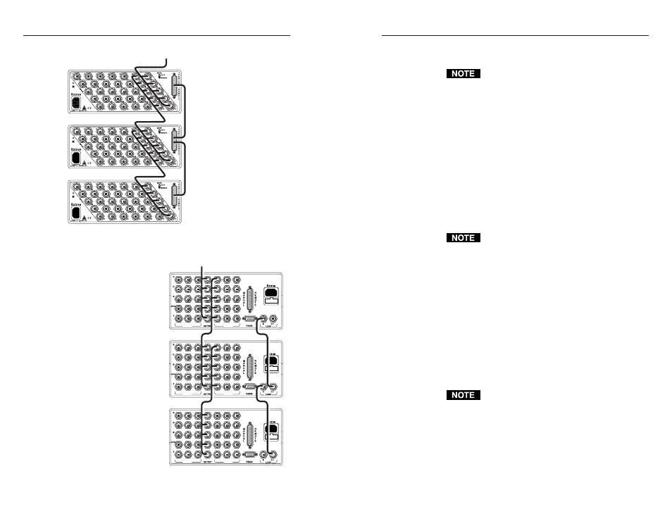
With the switchers connected as shown on page 2-12, input
selection occurs as shown below.
For SW AR
xi
and SW AR HV
xi
switchers, Loop
Out is on pin 24 of the 25-pin connector, and Loop
In is on pin 12. For SW AR MX and
SW AR MX HV switchers, Loop Out is on the
Loop Out BNC connector, and Loop In is on the
Loop In BNC connector.
• Any input selected by switcher A is seen at the output.
• An input selected on switcher B sends a loop control
signal (Loop Out) to switcher A (Loop In), causing
switcher A to select its input 6. Switcher B's selected
input is seen at the output.
• An input selected on switcher C sends a loop control
signal (Loop Out) to switcher B (Loop In), and then
from switcher B (Loop Out) to switcher A (Loop In).
Both switcher A and switcher B select input 6.
Switcher C's selected input is seen at the output.
Use high resolution cable, such as Extron’s
BNC-4 HR (BNC-5 HR for HV type switchers), for
input and output connections. BNC-4 and BNC-5
are available in various lengths. To limit signal
loss, use the shortest possible cable length.
For SW AR
xi
and SW AR HV
xi
switchers, the loop
control cables can be any standard wire.
For SW AR MX and SW AR MX HV switchers,
the loop control cables can be any 75-ohm coaxial
cable with BNC connectors.
Configuring switchers for looping
To configure three switchers for looping, do the following:
1.
Connect a BNC cable between the highest numbered
input of switcher A and the output of switcher B.
Refer to page 2-7 for instructions for cabling input
and output connections.
2.
Connect switcher A's output to the display device.
Connect another BNC cable from the highest
numbered input of switcher B to the output of
switcher C.
3.
For SW ARxi and SW AR HVxi switchers: Connect
switcher C’s contact remote connector pin-24 (Loop
Out) to switcher B’s contact remote connector pin 12
2-13
A
Output
B
C
2-12
Figure 21 —
Looping
SW AR HVxi
xi
xi
xi
xi
switchers
Figure 22 —
Looping
SW AR MX HV
switchers
90-240 VAC, 50/60 Hz
FUSE: 250V, 400mA SLO-BLO
INPUTS
INPUTS
5
3
1
2
4
6
90-240 VAC, 50/60 Hz
FUSE: 250V, 400mA SLO-BLO
INPUTS
INPUTS
5
3
1
2
4
6
90-240 VAC, 50/60 Hz
FUSE: 250V, 400mA SLO-BLO
INPUTS
INPUTS
5
3
1
2
4
6
Output
A
B
C