Installation – Extron Electronics SW MTP T Series User Guide User Manual
Page 9
SW MTP T Series Switchers • Installation
SW MTP T Series Switchers • Installation
Installation
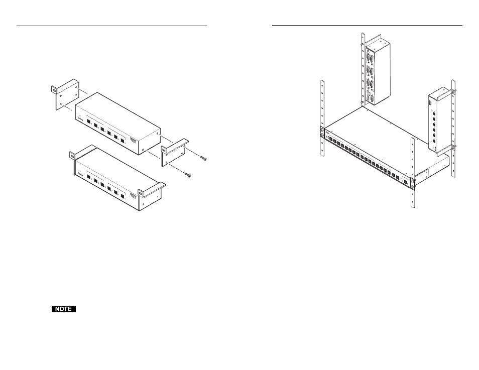
Back of the rack mounting
The SW MTP T can be mounted to the rear of a rack using the
Extron VersaTools
®
back-of-the-rack mount kit (part #70-367-01)
(figure 2-3). The kit allows the product to be vertically mounted
to the front or rear rack supports and facing either towards the
front or the rear of the rack.
AU
TO
SWITCH
6
5
4
SW
6 M
TP
T 1
5H
D A
1
MO
DE
2
NO
RM
AL
3
AU
TO
IN
PU
T
AUT
O
SW
ITCH
6
5
4
SW
6 M
TP
T 1
5H
D A
1
MO
DE
2
NO
RM
AL
3
AU
TO
IN
PU
T
Figure 2-3 — Attaching the back of the rack kit
1
.
Remove feet from the bottom of the SW MTP T if installed.
2
.
Remove two screws from one side of the unit. Retain the
screws for possible later reassembly without the bracket.
3
.
Attach one bracket to the side of the unit using the longer
screws included in the kit.
4
.
Repeat steps 2 and 3 on the other side of the unit.
5
.
Mount the unit to the rack using the two included rack
screws (figure 2-4). The SW MTP T can be vertically
mounted facing in either direction.
Only VersaTools products and most IP Link can be
mounted using the back of the rack mounting kit.
REMO
TE
IN
P
U
T
2
IN
P
U
T
1
AU
D
IO
RGB/A
UDIO
PRE-
PEAK
ON
OF
F
O
UT
P
U
T
L
R
PO
WER
1
2
V
0
.2
A
M
A
X
IN
P
U
T
4
IN
P
U
T
3
IN
P
UT
6
IN
P
U
T
5
MA
V S
ER
IE
S
AV
M
AT
RIX
SW
ITC
HE
R
I/O
AU
D
AU
DIO
SE
TU
P
PR
ES
ET
VID
IR
+dB
-dB
EN
TER
2
7
6
5
2
4
1
INPUTS
OUTPUTS
8
3
1
8
6
5
4
3
7
AU
T
O
SWITCH
6
5
4
SW6 MTP
T 15HD A
1
MODE
2
NORMAL
3
AU
T
O
INPUT
Figure 2-4 — Typical back of the rack installations
2-4
2-5