Appendix a, Reference information – Extron Electronics SW MTP T Series User Guide User Manual
Page 21
SW MTP T Series Switchers • Remote Control
Remote Control, cont’d
SW MTP T Series Switchers
A
Appendix A
Reference Information
Specifications
Part Numbers
Using the help system
For information about program features, you can access the help
program in any of the following ways:
•
From the Extron Electronics program group,
double-click on the Universal Switcher Help icon.
•
From within the Windows-based switcher control
program, click on the Help entry on the task bar.
•
From within the Windows-based switcher control
program, press the F1 key.
Contact Closure Remote Control
The Remote connector also provides a way to select an input to
the switcher using a remote contact closure device. Contact
closure control uses pins on the Remote connector that are not
used by the RS-232 interface. The contact closure pin
assignments are shown in the table on page 4-2.
To select a different input number using a contact closure
device, momentarily short the pin for the desired input number
to logic ground (pin 5). To force one of the inputs to be always
selected, leave the short to logic ground in place. The short
overrides front panel input selections.
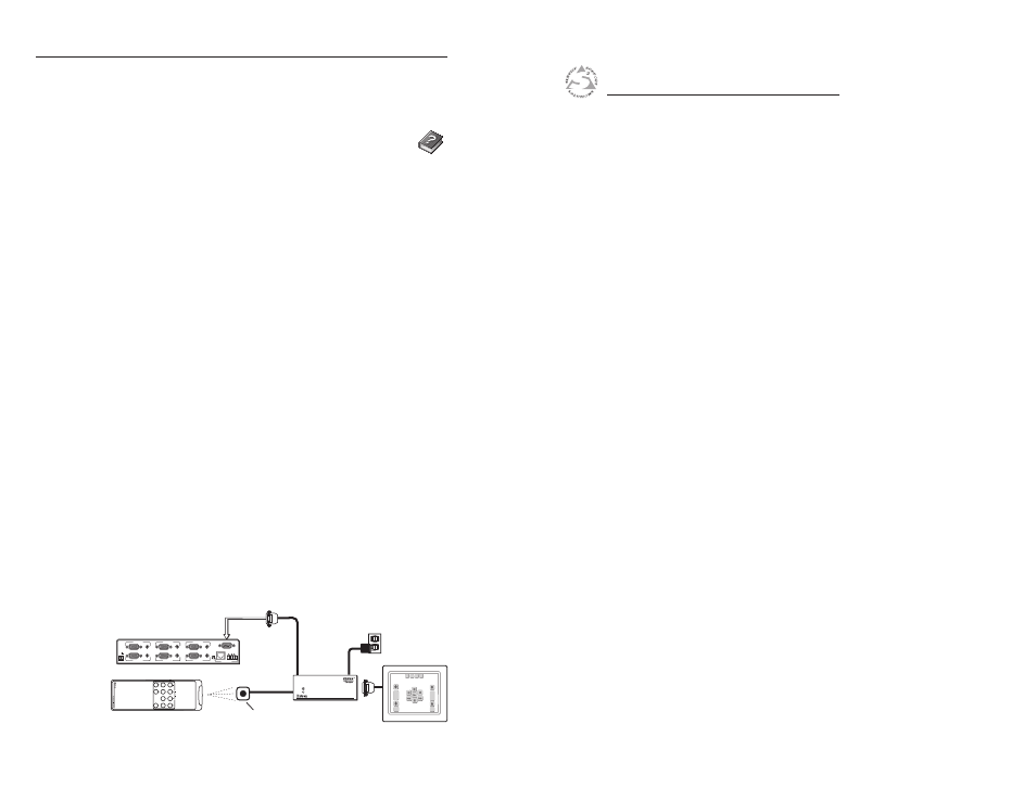
IR 102 Infrared Remote Control
The optional Extron IR 102 kit consists of the following
components:
•
IR 102 handheld remote control unit
•
VersaTools IR 102 remote receiver with 3’ cable and
RS-232 connector
•
IR detector with 6’ cable and captive screw connector
•
External 12 VDC power supply
Install and operate the remote control in accordance with the
IR 102 User’s Guide included with the remote.
IR 102 Remote
Control Recei
v
er
IR 102 Remote Control
IR Detector
3
'
Ca
b
le
6
'
Ca
b
le
Po
w
er
S
u
pply
RS-232
Control
S
W
6 MTP T 15HD A
REMOTE
100-240V 0.2A
INPUTS
IR-102
+10
IR 102
REMOTE
INPUT 2
INPUT 1
AUDIO
RGB/AUDIO
PRE-
PEAK
ON
OFF
OUTPUT
L
R
POWER
12V
0.2A MAX
INPUT 4
INPUT 3
INPUT 6
INPUT 5
Figure 4-5 — IR 102 Remote application
4-12