Installation, cont’d, Rear panel features and connections, Au to switch – Extron Electronics SW MTP T Series User Guide User Manual
Page 10: Furniture mounting, Power connection, Caution, Sw mtp t series switchers • installation, Figure 2-6 — sw6 mtp t switcher rear panel, Figure 2-7 — power connector wiring
SW MTP T Series Switchers • Installation
SW MTP T Series Switchers • Installation
Installation, cont’d
2-7
2-6
Furniture mounting
For furniture mounting, do not attach the rubber feet. Furniture
mount the switcher using the optional mounting kit
(part #70-212-01) (figure 2-5) as follows:
AU
TO
SWITCH
6
5
4
SW
6 M
TP
T 1
5H
D A
1
MODE
2
NORMAL
3
AU
TO
IN
PU
T
Figure 2-5 — Attaching the furniture mounting
brackets to an SW MTP T
1
.
Remove the rubber feet if they were previously installed
on the bottom of the switcher.
2
.
Attach the furniture mounting brackets to the switcher
with the provided machine screws.
3
.
Hold the switcher with the attached brackets against the
underside of the mounting surface. Mark the location of
the bracket’s screw holes on the surface.
4
.
Drill 3/32" (2 mm) diameter pilot holes, 1/4" (6.3 mm)
deep in the mounting surface at the marked locations.
5
.
Insert #8 wood screws into the four pilot holes. Tighten
each screw into the mounting surface until just less than
1/4" of the screw protrudes.
6
.
Align the mounting screws with the slots in the brackets
and place the switcher against the surface, with the screws
through the bracket slots.
7.
Slide the switcher slightly forward or back, then tighten all
four screws to secure the unit in place.
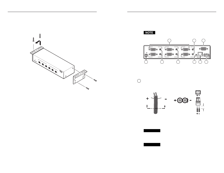
Rear Panel Features and Connections
All connectors are on the rear panel (figure 2-6). Depending on
the model of the switcher, the number of connectors on the rear
panel varies.
The SW2 MTP T and SW4 MTP T switchers have fewer
input connectors but are otherwise identical.
REMOTE
INPUT 2
INPUT 1
AUDIO
RGB/AUDIO
PRE-
PEAK
ON
OFF
OUTPUT
L
R
POWER
12V
0.5A MAX
INPUT 6
INPUT 5
INPUT 4
INPUT 3
7
1
5
4
6
2
3
3
3
Figure 2-6 — SW6 MTP T switcher rear panel
Power connection
1
Power connector—
Plug the external 12 VDC power supply into
this 2-pole captive screw connector. Figure 2-7 shows how to
wire the connectors.
Power Supply
Output Cord
Captive Screw
Connector
0.2” (5 mm)
SECTION A–A
Ridges
Smooth
A
A
Figure 2-7 — Power connector wiring
CAUTION
Power supply voltage polarity is critical. Incorrect
voltage polarity can damage the power supply and
the switcher. Identify the power cord negative lead
by the ridges on the side of the cord (figure 2-7).
CAUTION
The length of the exposed (stripped) copper wires is
important. The ideal length is 0.2" (5 mm).
Longer bare wires can short together. Shorter wires
are not as secure in the captive screw connectors
and could be pulled out.